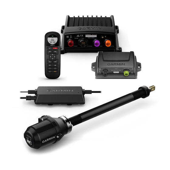
Garmin Reactor 40 Kicker Manual de instruções de instalação - Página 4
Procurar online ou descarregar pdf Manual de instruções de instalação para Equipamento marítimo Garmin Reactor 40 Kicker. Garmin Reactor 40 Kicker 29 páginas.
Também para Garmin Reactor 40 Kicker: Manual de configuração (6 páginas), Manual de configuração (8 páginas)

Item Description
ECU power cable
CCU cable
Throttle actuator
Steering actuator
Mounting and Connection Considerations
The autopilot components connect to each other and to power using the included cables. Ensure that the
correct cables reach each component and that each component is in an acceptable location before mounting or
wiring any components.
CCU Mounting and Connection Considerations
• The CCU is the primary sensor of the Reactor 40 Kicker autopilot system. For best performance, observe
these considerations when selecting a mounting location.
◦ A handheld compass should be used to test for magnetic interference in the area where the CCU is to be
mounted(Testing a Location for Magnetic Interference, page
◦ The CCU should be mounted on a rigid surface for best performance.
• Mounting screws are provided with the CCU. If you use mounting hardware other than the provided screws,
the hardware must be quality stainless or brass material to avoid magnetic interference with the CCU.
Test any mounting hardware with a handheld compass to make sure no magnetic fields are present in the
hardware.
• The CCU cable connects the CCU to the ECU and is 5 m (16 ft.) long.
◦ If the CCU cannot be mounted within 5 m (16 ft.) of the ECU, extension cables are available from your local
Garmin dealer or at www.garmin.com.
◦ This cable must not be cut.
4
Important Considerations
You must connect the ECU to a 12 to 24 Vdc power source. To extend this cable, use
the correct wire gauge
(Power Cable Extensions, page
To extend this cable to reach the ECU, you may need to use cable extensions (sold
separately)
(CCU Mounting and Connection Considerations, page
The throttle actuator controls the speed of the motor.
The throttle actuator power cable cannot be cut or extended.
This diagram shows only the electrical connection to the throttle actuator. Detailed
installation instructions are included with the throttle actuator.
The steering actuator steers the motor.
The steering actuator power cable cannot be cut or extended.
9).
5).
4).
