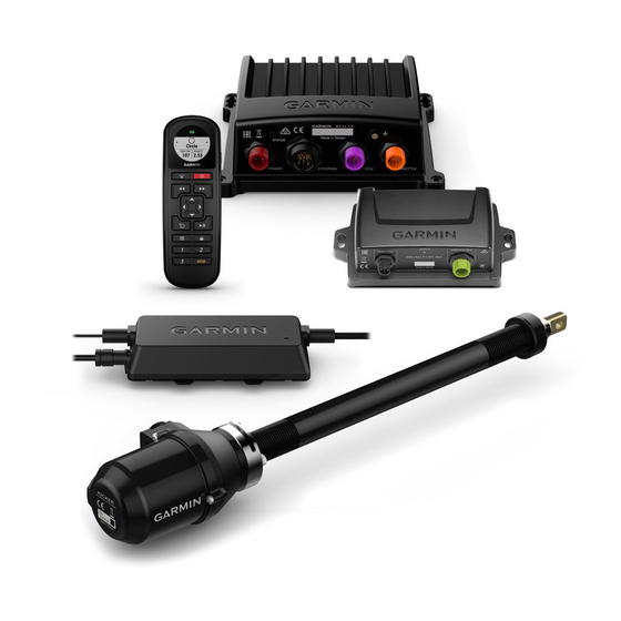
Garmin Reactor 40 Kicker Manual de instruções de instalação - Página 6
Procurar online ou descarregar pdf Manual de instruções de instalação para Equipamento marítimo Garmin Reactor 40 Kicker. Garmin Reactor 40 Kicker 29 páginas.
Também para Garmin Reactor 40 Kicker: Manual de configuração (6 páginas), Manual de configuração (8 páginas)

Steering Actuator Installation and Connection Considerations
You must install the steering actuator in a tilt tube made of stainless steel. Installing the steering actuator in a
tilt tube made of a material other than stainless steel will cause rust to develop inside of the tilt tube, and
eventually the steering actuator will seize. Mechanical damage to the steering actuator caused by attempting to
free a seized push rod is not covered by the product warranty.
• The steering actuator mounts in the tilt tube of your motor and uses a steering arm and linkage system to
steer.
• You can install the steering actuator from either side of the tilt tube.
• You must install the steering actuator before permanently mounting the ECU.
• You cannot extend the cable that connects the steering actuator to the ECU.
• Popular motor manufacturers such as Honda
stainless. You must replace the original tilt tube with a stainless steel tilt tube before installing the steering
actuator.
• Even when installing the steering actuator in a stainless steel tilt tube, if you use your boat in saltwater, you
should perform the routine maintenance at least twice per year
Storage Information, page
Throttle Actuator Mounting and Connection Considerations
• The throttle actuator mounts inside the motor housing and connects to the throttle to control the speed.
• You should follow the instructions provided with the throttle actuator for assembly and mounting details.
• You must install the throttle actuator before permanently mounting the ECU.
• You cannot extend the cable that connects the throttle actuator to the ECU.
NMEA 2000 Connection Considerations
• The CCU and the helm control must connect to a NMEA 2000 network.
• If your boat does not already have a NMEA 2000 network, one can be built using the included NMEA 2000
cables and connectors
• To use the advanced features of the autopilot, optional NMEA 2000 devices, such as a wind sensor, a water-
speed sensor, or a GPS device, can be connected to the NMEA 2000 network.
Installation Procedures
To avoid possible personal injury, always wear safety goggles, ear protection, and a dust mask when drilling,
cutting, or sanding.
When drilling or cutting, always check what is on the opposite side of the surface to avoid damaging the vessel.
After you have planned the autopilot installation on your boat and satisfied all of the mounting and wiring
considerations for your particular installation, you can begin mounting and connecting the components.
Helm Control Installation
A dedicated helm control is not included in all autopilot packages. If you install the autopilot without a dedicated
helm control, the autopilot CCU must be connected to the same NMEA 2000 network as a compatible Garmin
chartplotter to configure and control the autopilot system.
Detailed mounting instructions are included in the helm control box.
6
®
and Yamaha
19).
(Building a Basic NMEA 2000 Network for the Autopilot System, page
NOTICE
®
commonly use tilt tubes made of steel that is not
(Steering Actuator Routine Maintenance and
CAUTION
NOTICE
17).
