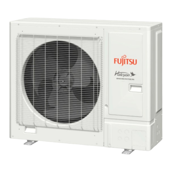
Fujitsu 24LMAS1 Manual de instalação - Página 3
Procurar online ou descarregar pdf Manual de instalação para Ar condicionado Fujitsu 24LMAS1. Fujitsu 24LMAS1 17 páginas. Outdoor unit

• The following installation parts are supplied. Use them as required.
• Keep the Installation Manual in a safe place and do not discard any other accessories
until the installation work has been completed.
Name and shape
Installation manual
Drain pipe
Drain cap
One set of following parts are necessary installation of this product.
Additional materials
Connection pipe assembly
Decorative tape
Connection cable
Vinyl tape
Wall pipe
Wall cap
2.3. Pipe requirements
• Do not use existing pipes.
• Use pipes that have clean external and internal sides without any contamination which
may cause trouble during use, such as sulfur, oxide, dust, cutting waste, oil, or water.
• It is necessary to use seamless copper pipes.
Material: Phosphor deoxidized seamless copper pipes.
It is desirable that the amount of residual oil is less than 0.004 oz/100 ft (40 mg/10 m).
• Do not use copper pipes that have a collapsed, deformed, or discolored portion
(especially on the interior surface). Otherwise, the expansion valve or capillary tube
may become blocked with contaminants.
• Improper pipe selection will degrade performance. As an air conditioner using R410A
incurs pressure higher than when using conventional refrigerant, it is necessary to
choose adequate materials.
• Thicknesses of copper pipes used with R410A are as shown in the table.
• Never use copper pipes thinner than those indicated in the table even if they are
available on the market.
Thicknesses of Annealed Copper Pipes
Pipe outside diameter [in (mm)]
1/4 (6.35)
3/8 (9.52)
1/2 (12.70)
5/8 (15.88)
3/4 (19.05)
2.3.1. Refrigerant pipe size and allowable piping length
• Keep the piping length between the indoor unit and outdoor unit within the allowable
tolerance.
• The maximum lengths of this product are shown in the table. If the units are further
apart than this, correct operation cannot be guaranteed.
Pipe diameter <Liquid/Gas>
(Standard)
in (mm)
Max. piping length (L1)
ft (m)
Min. piping length (L1)
ft (m)
Max. height difference (H1)
<Indoor unit to outdoor unit>
ft (m)
View (Example)
Qty
Description
This manual
1
For outdoor unit drain piping work
1
(May not be supplied, depending on
the model.)
3
Saddle
Tapping screws
Drain hose
Sealant
M10 bold, nut
CAUTION
Thickness [in (mm)]
0.032 (0.80)
0.032 (0.80)
0.032 (0.80)
0.039 (1.00)
0.047 (1.20)
CAUTION
3/8 (9.52) / 5/8 (15.88)
164 (50)
17 (5)
98 (30)
L1
H1
2.3.2. Protection of pipes
• Protect the pipes to prevent the entry of moisture and dust.
• Especially, pay attention when passing the pipes through a hole or connecting the
end of a pipe to the outdoor unit.
Location
Working period
1 month or more
Outdoor
Less than 1 month
Indoor
-
2.4. Power source
• Always use a special branch circuit and install a special receptacle to supply power
to the room air conditioner.
• Use a circuit breaker and receptacle matched to the capacity of the air conditioner.
• Install a leakage circuit breaker in accordance with the related laws and regulations
and electric company standards.
• The circuit breaker is installed in the permanent wiring. Always use a circuit that can
trip all the poles of the wiring and has an isolation distance of at least 1/8 in (3 mm)
between the contacts of each pole.
• The power source capacity must be the sum of the air conditioner current and the cur-
rent of other electrical appliances. When the current contracted capacity is insufficient,
change the contracted capacity.
• When the voltage is low and the air conditioner is difficult to start, contact the power
company the voltage raised.
2.5. Electrical requirements
• Be sure to install a breaker of the specified capacity.
• Before the electrical work, confirm electrical standards and regulations in each
country, region, or installing place. Then select appropriate cables and breakers that
comply with them.
• This unit must be connected to a power supply with impedance of 0.419 ohm and below.
If the power supply does not satisfy this requirement, please consult the power supplier.
Voltage rating
Operating range
Cable
Model
18
Power supply cable
24
Refer to the installation manual of the indoor unit for
Connection cable
Cable Length: Limit voltage drop to less than 2%. Increase cable gauge if voltage drop is 2%
or more.
MINIMUM CIRCUIT
Model
AMPACITY
18
17.1A
24
19.6A
• Select the correct cable type and size according to the country or region's regulations.
• Select the breaker so that enough load current can pass through it.
• Before starting work check that power is not being supplied to all poles of the indoor
unit and outdoor unit.
• Install all electrical works in accordance to relevant national regulations.
• Install the disconnect device with a contact gap of at least 1/8 in (3 mm) in all poles
nearby the units. (Both indoor unit and outdoor unit)
• Install the circuit breaker nearby the units.
Protection method
Pinch pipes
Pinch or tape pipes
Pinch or tape pipes
WARNING
CAUTION
CAUTION
1 ø 208/230 V (60 Hz)
187-253 V
Type
Remarks
14AWG
2 cable + Ground (Earth),
1 ø 208/230 V
12AWG
the connection cable specifications.
MAX. CKT. BKR.
20A
20A
En-3
