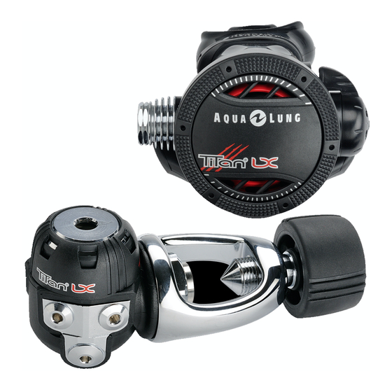
Aqua Lung Titan Manual de manutenção - Página 8
Procurar online ou descarregar pdf Manual de manutenção para Controlador Aqua Lung Titan. Aqua Lung Titan 20 páginas. Second stage
Também para Aqua Lung Titan: Boletim Técnico (4 páginas), Manual de serviço (19 páginas)

8
4.
Using tool p/n 125727, engage the slotted head of the
crown (14) and drive it in clockwise as far as the tool will
allow. If the tool is not available, use a medium flathead
screwdriver to drive the crown in as far as it will go and then
back it out 3 revolutions.
5.
Stand the inlet fitting (13)
vertical on a flat surface
with the sealing edge of
the crown (14) facing up
inside. Lay the previously
used LP seat (23) inside
the inlet fitting, over
the sealing edge of the
crown.
NOTE:
It is essential to use a spare LP seat in order to
prevent damage to the new seat while performing the fol-
lowing steps of the reassembly procedure.
6.
Place the poppet bearing (20) over the pin of the extrac-
tion tool with the square feature facing up. Guide the pin
of the tool into the open end of the valve body (19) and out
through the square hole in its center. While sighting through
the top of the valve body, rotate the tool as needed to align
the square feature of the poppet bearing with the square
hole, and press the tool upward to seat the bearing securely
in place. When finished, check to ensure that the top of the
poppet bearing is flush with the top of the valve body.
7.
Press the new LP seat (23)
into the cavity in the head
of the poppet (22), with the
smooth side facing out.
8.
Stand the poppet (22) on
its head inside the top of
the inlet fitting (13) and
on top of the old LP seat.
Place the spring (21) over
the poppet shaft.
9.
Hold the inlet fitting (13)
secure, and mate the valve
body (19) with poppet
bearing down over the
poppet shaft (22). Press
the valve body downward
to compress the spring
while turning it clockwise
to engage the threads of
the inlet fitting, and then
continue turning it slowly
until the threaded portion
of the poppet shaft stands
outside the poppet bearing
(20).
CAUTION:
If resistance is felt, immediately stop
and unscrew the valve body from the inlet fitting
to check the alignment of the poppet shaft and
poppet bearing. Excessive force and misalign-
ment will otherwise result in damage to the pop-
pet bearing, requiring its replacement.
10.
Lay the arms of the lever
(18) inside the groove
of the valve body (19),
straddling the poppet
shaft (22), so that the
curved portion of the
lever faces away from the
air outlet hole.
