Dell PowerVault TL2000 Instruções de anexação - Página 10

Procurar online ou descarregar pdf Instruções de anexação para Armazenamento Dell PowerVault TL2000. Dell PowerVault TL2000 17 páginas. Tape library
Também para Dell PowerVault TL2000: Notas de lançamento (3 páginas), Começar a trabalhar (38 páginas), Perguntas frequentes (26 páginas), Manual de início rápido (7 páginas), Manual do software (16 páginas), Manual de configuração (22 páginas), Manual de informações importantes (10 páginas), Adenda ao Manual do Utilizador (2 páginas), Manual de iniciação (3 páginas), Brochura (4 páginas), Manual do utilizador (20 páginas)
Dell PowerVault TL2000 Instruções de anexação
iSCSI for TL-Series Tape Libraries
SEPTEMBER 2008
SECTION 5

STORAGE TARGETS : TL2000 / TL4000

Set-up of the TL2000/TL4000 with iSCS-to-SAS bridge card follows the same process:

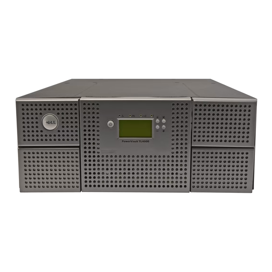
Figure 13 : TL2000 / TL4000 1Gb iSCSI to SAS Bridge

Select Connections and set the IP address and frame size for the port(s).
SECTION 6

CONFIGURING AN MD3000i

Assuming a Dell PowerVault MD3000i, an iSCS disk array, is connect to the example network,
the initial configuration would require physically installing & powering on the unit and then in-
stalling and running Modular Disk Storage Manager (MDSM) on the host computer. After in-
stallation of MDSM has been completed on the host computer, the disk array must be discov-
ered by the host. The default management IP addresses for the MD3000i are
192.168.128.101 for Controller 0 and 192.168.128.101 for Controller 1. After these addresses
are used to establish connectivity to the unit, the remaining steps include setting up disk
groups, creating virtual disks, and assigning LUNs (Logical Unit Numbers) to the virtual disks.
More information on this can be found in the documentation for the MD3000i on
www.support.dell.com. To configure the iSCSI settings, go to the iSCSI tab in MDSM (Figure
15). To configure the host ports, select "Configure iSCSI Host Ports" (Figure 16). There are 2
Host Ports on each controller, and they are, by default, assigned IP addresses
192.168.130.101-102 and 192.168.131.101-102. The Advanced button will enable the user to
change settings for VLAN support, Ethernet priority, TCP listening port, and Ethernet Jumbo
frames. Enable Jumbo Frames and select 9000 for the Bytes/frame size.

Figure 14 : Set IP Address and Frame Size

10