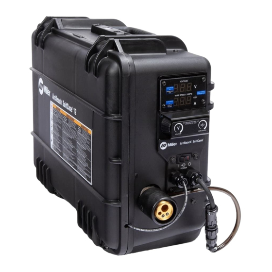
Miller ArcReach SuitCase Non-CE Manual do Proprietário - Página 42
Procurar online ou descarregar pdf Manual do Proprietário para Sistema de soldadura Miller ArcReach SuitCase Non-CE. Miller ArcReach SuitCase Non-CE 48 páginas.

7-5.
Diagnostics
Shown On Display
HLP 11
HLP 12
HLP 13
HLP 14
HLP 15
Error Indications - Error conditions are indicated by a "HLP" message on the display, or by the blinking of the Red LED on Motor Board PC1. To
view the Red LED, turn Off power source, remove shroud, and turn power source On. The number of blinks in this period indicates the type of er-
ror. If an error condition does not exist on the motor board, the Red LED is on steady.
Communication Error - The communication error occurs 2.5 seconds after a loss of communication between the motor board and the meter
board. The user may continue to weld with this error. The error may be cleared by turning power Off, waiting a minimum of two seconds, and
turning power On.
Trigger Error - The trigger error occurs if the user has fed approximately 35 feet (10.7 meters) of wire without striking an arc. The error may be
cleared by releasing the trigger.
Motor Overload Error - The motor overload error can indicate that the motor has been drawing too much current for too long, To remedy this, re-
duce the wire feed speed or the wire feeder torque load/duty cycle. The error may be cleared by turning power Off, waiting a minimum of two sec-
onds, and turning power On.
Bus Bar Overheat Error - The bus bar overheat error can be caused by the arc drawing too much current for too long or degraded/improper
weld circuit connections. To remedy this, reduce the weld amperage or duty cycle and check/repair/clean the weld cable connections including
the welding gun power pin.
Tach Error - May indicate motor is overloaded. If a tach error occurs, feeder will continue to function. When the trigger is released, a tach error
will be indicated on the front panel, or red LED blinks on Motor Control Board (PC1). The tach error will be cleared when the feeder is retriggered.
If error persists, have feeder serviced. Tach error may also be generated if DIP switch SW1 on Motor Control Board (PC1) is set incorrectly (See
Section 5-12).
OM-278792 Page 36
�
Complete Parts List is available at www.MillerWelds.com
Error Indicators
RED LED on Motor Board PC1
1 Blink
2 Blinks
3 Blinks
4 Blinks
5 Blinks
Error
Communication Error
Trigger Error
Tach Error
Motor Overload Error
Bus Bar Overheat Error
