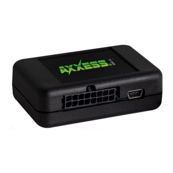
Axxess AXi-CANBOX1 Manual de instalação - Página 4
Procurar online ou descarregar pdf Manual de instalação para Equipamento de gravação Axxess AXi-CANBOX1. Axxess AXi-CANBOX1 11 páginas.

Wiring legend and description
DO NOT CONNECT WIRES BELOW WHEN USED IN
CONJUNCTION WITH AXi PLUG AND PLAY HARNESS.
Red Wire: Constant +12V power input.
Must connect to constant power source, can usually be found at
the main power plug on the back of the radio or at another source
where AXi-CANBOX1 is installed. Do not connect to accessory or
ignition power source. Connecting to +12V constant power will
not drain battery, interface goes into sleep mode after key is
removed and doors are locked.
Black Wire: Ground connection.
Must connect to a ground source, can usually be found at the
main power plug on the back of the radio or at another source
where AXi-CANBOX1 is installed. Do not connect to chassis
ground or radio chassis.
CAN Wires: If installation is going to be performed without plug
and play harness CAN High and CAN Low Wires must be cut and
the AXi-CANBOX1 will be installed in line.
Orange Wire: CAN High radio side.
Connect orange wire to radio side of vehicles CAN High wire.
Green Wire: CAN Low radio side.
Connect green wire to radio side of vehicles CAN Low wire.
Yellow Wire: CAN High car side.
Connect yellow wire to car side of vehicles CAN High wire.
White Wire: CAN Low car side.
Connect white wire to car side of vehicles CAN Low wire.
Blue Wire: External activation switch.
Used only in certain applications.
Purple Wire: Not used, do not connect.
Micro USB: Used for programing and updating
AXi-CANBOX1 must be programmed with a vehicle specific
software before installation starts. Please see pages 7-9 for
details.
Status LED: Blinks when CAN wires properly connected.
4
