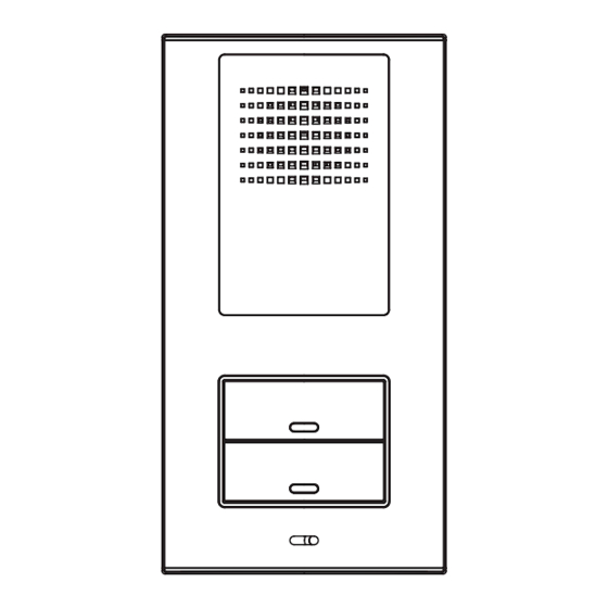
Bitron Video AV2058/51 Manual de instruções - Página 9
Procurar online ou descarregar pdf Manual de instruções para Sistema de intercomunicação Bitron Video AV2058/51. Bitron Video AV2058/51 10 páginas. Door-phone kit 4+n 12 vca
Também para Bitron Video AV2058/51: Manual de instruções (11 páginas)

PROTECTION CONTRE LES COURTS-CIRCUITS SUR L'APPEL
Un éventuel court-circuit sur les bornes d'appel provoquera l'intervention du dispositif de protection qui
interrompt les appels pendant plusieurs secondes. Au terme de ce délai, la platine extérieure est à nouveau en
mesure de générer un nouvel appel ; si le court-circuit n'est pas éliminé, le cycle se répète.
CONNEXION DES TOUCHES POUR APPEL INTERPHONE DE TYPE ÉLECTRONIQUE
Pour KIT mono-famille AV2058/51
Raccorder la borne C de la platine extérieure à une extrémité de la touche montée sur la platine AV1878/10.
Raccorder la borne "C7" du poste audio T-LINE AV1407/002 à l'autre extrémité de la touche d'appel
Pour KIT bi-famille AV2058/52
Raccorder la borne C de la platine extérieure à une extrémité de la touche montée sur la platine AV1878/12 de
manière à créer un commun d'appel au moyen d'une barrette en fil.
Raccorder la borne "C7" du premier poste audio T-LINE AV1407/002 à l'autre extrémité de la touche d'appel
de l'utilisateur P1.
Raccorder la borne "C7" du deuxième poste audio T-LINE AV1407/002 à l'autre extrémité de la touche d'appel
de l'utilisateur P2.
CONNEXION DES TOUCHES POUR APPEL INTERPHONE DE TYPE VIBREUR
Pour KIT mono-famille AV2058/51
Raccorder la borne ~ de la platine extérieure à une extrémité de la touche montée sur la platine AV1878/10.
Raccorder la borne "C7" du poste audio T-LINE AV1407/002 à l'autre extrémité de la touche d'appel
Pour KIT bi-famille AV2058/52
Raccorder la borne ~ de la platine extérieure à une extrémité de la touche montée sur la platine AV1878/12 de
manière à créer un commun d'appel au moyen d'une barrette en fil.
Raccorder la borne "C7" du premier poste audio T-LINE AV1407/002 à l'autre extrémité de la touche d'appel
de l'utilisateur P1.
Raccorder la borne "C7" du deuxième poste audio T-LINE AV1407/002 à l'autre extrémité de la touche d'appel
de l'utilisateur P2.
Pour le reste des branchements électriques, faire référence aux schémas de l'installation au bas du
manuel.
FIXATION DE LA PLATINE AU MUR
1)
Ouvrir le combiné soulevant la coiffe, en insérant un tournevis dans les fentes inférieures (Fig. 4).
2)
Après avoir fait les trous dans le mur, insérer les chevilles (fournies) et faire passer les fils dans la fente
centrale. Bloquer, à l'aide des vis, le combiné au mur en utilisant les trous appropriés. Brancher ensuite
les fils au combiné, comme indiqué dans le schéma électrique.
Pour les sections des conducteurs se référer à la table relative (Fig. 1).
3)
Refermer le combiné par pression en veillant à ne pas pincer les fils entre les deux coquilles.
12
CONNECTIONS
The following rules must be observed for connections:
Respect the instructions shown in the table (Fig. 1) carefully.
-
-
Avoid installing system wires close to electrical mains wires (they should be at least 30 cm apart).
-
Connect the ground wires exactly as shown in the diagrams to avoid buzzing.
Position the transformer at a maximum distance from the door panel of 20 metres.
Use 1 mm² wires for connecting terminals ~ and 0. Also respect the connections shown on the diagram
to prevent noise.
VOLUME ADJUSTMENT
The entrance panel audio unit settings are optimal for a system of average size by default.
The settings may however need to be changed.
Proceed as follows in such a case
-
External volume: turn trimmer EXT clockwise to turn the volume up and anticlockwise to turn it down.
-
Internal volume: turn trimmer INT in a similar way.
Turn down both volumes slightly if feedback loop howl occurs to eliminate the problem.
"RC" CALL CONFIRMATION EXCLUSION
The entrance panel generates a confirmation tone when the doorphone call is sent to the doorphone. This tone
may be deactivated by opening the "RC" jumper near the entrance unit terminal board as shown in Fig. 3.
CALL SHORT CIRCUIT PROTECTION
The protection system will cut off calls for a few seconds in the event of a calling terminal short circuit. After
this time, the entrance panel will be able to generate a new call. The cycle will be repeated if the short circuit
persists.
ELECTRONIC DOORPHONE CALL BUTTON CONNECTIONS
For AV2058/51 one-villa kit
Connect terminal C of the door panel to a terminal of the button fitted on the AV1878/10 panel.
Connect terminal "C7" of the T-LINE AV1407/002 doorphone to the other calling button terminal.
For AV2058/52 two-villa kit
Connect terminal C of the door panel to a terminal of the two buttons fitted on the AV1878/12 panel creating
a call common using a wire jumper.
Connect terminal "C7" of the first T-LINE AV1407/002 doorphone to the other calling button terminal of user
P1.
Connect terminal "C7" of the second T-LINE AV1407/002 doorphone to the other calling button terminal of
user P2.
BUZZER DOORPHONE CALL BUTTON CONNECTIONS
For AV2058/51 one-villa kit
Connect terminal ~ of the door panel to a terminal of the button fitted on the AV1878/10 panel.
Connect terminal "C7" of the T-LINE AV1407/002 doorphone to the other calling button terminal.
For AV2058/52 two-villa kit
Connect terminal ~ of the door panel to a terminal of the two buttons fitted on the AV1878/12 panel creating
a call common using a wire jumper.
DS90335-002
DS90335-002
(Fig. 2t)
9
