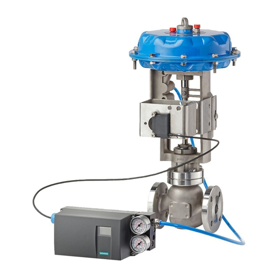
15900-766
PARTS, KIT 16152-665
Description
Manifold
Standoff (for Linkage U)
Feedback Pin (for Linkage P)
O-Ring
M8 x 25 Socket Hd. Cap Screw
M8 Split Lockwasher
M6 x 35 Low Socket Hd. Cap Screw
M6 Split Lockwasher
1/4 NPT Pipe Plug
G1/4 Pipe Plug
INSTALLATION
Refer to the following procedure and to the positioner and actuator installation instructions while
performing the installation. The current revision of the positioner instruction
Internet site. See Customer/Product Support later in this Instruction for the URL.
Before beginning the installation, note the following cautions.
CAUTION
CAUTION
Two installations are described below: Linkage P and Linkage U. Feedback linkage components differ
and this affects the installation procedure, as indicated in several steps below.
1. Open the supplied kits and check the included parts against the above parts list and the drawing on
page 1. Note whether feedback linkage components are for a Linkage P or Linkage U installation; see
the exploded view drawing on page 1.
2. Mount the manifold on the actuator – Place an O-ring in the recess in the manifold and use two M8 x
25 socket head screws to secure the manifold to the actuator.
3. Mount feedback parts on the actuator:
•
Linkage P – Thread the feedback pin into the stem block. Do not tighten at this time.
•
Linkage U – Fasten the standoff, V-blocks, and U-channel to the stem block using two supplied
M8 x 12 socket head screws and lockwashers. Do not tighten at this time.
4. Mount feedback parts on the positioner:
•
Linkage P – 1) Insert the threaded end of the linear adapter into
the rectangular hole in the feedback lever; see detail at right.
Install and tighten the supplied nut and lockwasher. Note: Ignore
the text on the feedback lever. 2) Place the linear adapter on the
positioner input shaft and tighten the adapter setscrew on the
flat on the shaft. If desired, a small amount of thread locking
solution can be placed on the setscrew threads.
1
PS2: SIPART PS2 Electropneumatic Positioners for Linear and Rotary Actuators, P/N A5E00074631
Do not apply supply pressure to the actuator or the valve
positioner during the installation process. Applying supply
pressure before the equipment is properly mounted could cause
unexpected movement that could lead to personal injury or
equipment damage.
Do not exceed the maximum actuator and valve positioner air
pressures stated in the manufacturer's literature. Exceeding
these ratings could cause personal injury or equipment damage.
2
Quantity
1
1
1
2
4
2
2
2
1
1
1
is available at the Siemens
Adapter setscrew
on far side for
easier access.

