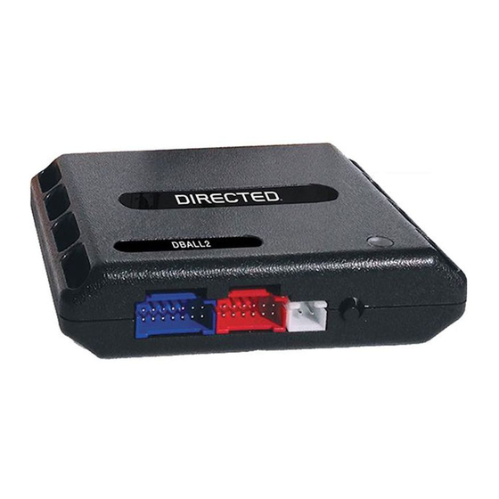
Platform: DBALL2
Firmware: GM6
Installation Type 2 (without RFLCHGM)
WARNING!
We recommend using the Wiring Diagram (
RFLCHGM) will draw 15-20mA more on the vehicle, when it is parked and the engine is turned off.
Using Wiring Diagrams (
without
wire opening. To preserve OEM remote starter functionality, use the Wiring Diagram (
Immobilizer Control Module
(under ignition switch,
black connector)
5 4
3 2 1
(-) Ground: Black
(+) 12V:
or Black/White,
pin 1
pin 3
(+) Accessory:
Brown, pin 2
Transponder Accessory: Yellow/Red: 11
Transponder (-) Ground: Brown/Red: 12
RAP Off: Refer to the Vehicle
Wiring Reference Chart on
page 9 for wire color and
location.
Not required in D2D mode.
Tach wire is an optional connection required on some remote starters, which do not support a tach signal in D2D.
[1]
Trunk Release can be on TRUNK or AUX1 depending on the vehicle, see Features & Option List section to change its operation.
[2]
Heated seat feature must be enable, see Features & Option List section.
[3]
Do not use GWR (Status) wire to activate heated seat feature. This wire needs to see a pulse after start for proper operation.
If the RAP Off wire is not connected, the radio will turn OFF but some lights will remain ON in the central console for 10 minutes. Connect this wire
[4]
(Green/Black, pin 2/12) to the driver door sense trigger (Gray/Black) to avoid this issue. RAP Off: Refer to page 9 for wire color and location.
With the exception of the OBDII Diagnostic connector, all connectors are displayed from the wire side (unless specified otherwise).
with
RFLCHGM) on page 3, especially if the vehicle is not used daily. The Wiring Diagram (
RFLCHGM) can deactivate OEM remote starter functionality, OEM fob and smart phones, due to the accessory
(-) Ground
(+) 12V
(-) Parking Lights
Ignition Switch
Refer to the Vehicle Wiring
Reference Chart on page 9
for wire color and location.
(+) Ignition: Pink
Single Wire CAN:
Green, pin 1
1
8
9
16
Single Wire CAN: Lt. Green: 1
(+) 12V
(+) 12V: Brown: 7
(+) Ignition: Yellow: 8
Transponder (+) 12V: Orange/Red: 10
(+) 12V
(+) 12V: Red: 13
(-) Ground
(-) Ground: Black: 14
(-) RAP Off: Green/Black: 2
[4]
(-) Door Status Output: Green/White: 3
(-) Trunk Status Output: Red/Black: 4
(AC) Tach Output: Violet/White: 5
[1]
(+) Brake Status Output: Gray: 6
(+) Accessory Output: Gray/Black: 7
(-) Hood Status Output: Blue/Red: 12
with
RFLCHGM) on page 3.
(-) Hood Status Input
(+) Brake Status Input
(AC) Tach Input
[1]
(-) Trunk Status Input
(-) Door Status Input
(-) Ground
(+) 12V
(-) Parking Lights
Connector
Key Side
Diagnostic Connector OBDII
(connector side view)
RF
DBALL/
Prog. Button
DBALL2
LED
(-) Lock Output
(-) Unlock Output
(-) Trunk Release Output
(-) AUX1 Output
(-) AUX2 Output
[3]
(+) Starter Output
(+) Ignition Input/Output
(-) GWR (Status)
Diode
Please note that pin
numbers may vary from
vehicle to vehicle. Test the
wires appropriately for a
successful installation.
10: Blue/White: (-) GWR (Status) Input
9: Pink: (+) Ignition Input
8: Violet: (+) Starter Input
5: Violet/Black: (-) AUX2 Heated Seat Input
4: White/Violet: (-) AUX1 Rear Hatch Input
3: Red/White: (-) Trunk Release/Tail Glass (if applicable) Input
2: Blue: (-) Unlock Input
1: Green: (-) Lock Input
(+)12V
RX
(-) Ground
TX
XKD2D65
© 2015 Directed. All rights reserved.
Rev.: 20151221
Page 4
without
[3]
[2]

