Directed Xpresskit DBALL2 Manual de instalação - Página 3

Procurar online ou descarregar pdf Manual de instalação para Por fechaduras Directed Xpresskit DBALL2. Directed Xpresskit DBALL2 16 páginas. Ford5 remote start ready (rsr) installation
Também para Directed Xpresskit DBALL2: Manual de instalação (12 páginas), Manual de instalação (19 páginas), Manual de instalação (18 páginas), Manual (14 páginas), Manual de instalação (13 páginas), Manual de instalação (14 páginas), Manual de instalação (19 páginas), Manual de instalação (16 páginas), Manual de instalação (20 páginas), Manual de instalação (15 páginas), Manual de instalação e referência rápida (16 páginas), Manual de instalação (18 páginas), Manual de instalação (18 páginas), Manual de instalação (16 páginas), Manual (19 páginas)
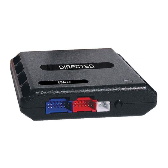
Directed Xpresskit DBALL2 Manual de instalação
Platform: DBALL2
Firmware:
CHRYSLER8 Remote Start Ready (RSR) Installation

Installation without T-Harness

C2 2-pin Blue conn.
(located at BCM,
under driver side dash)
B
A
(+) 12V:
Red, pin A
Immo. Data (veh. side): Orange/Yellow: 9
(MUX) Parking Light Output: Violet/Brown: 9
Immo. Data (veh.side): Yellow/Black: 10
Immo. Data:
White/Lt Green: pin 5
6
5
4
3
2
1
Ignition Node
(black connector)
Not required in D2D mode.
Tach wire is an optional connection required on some remote starters, which do not support a tach signal in D2D.
[1]
Required for RAP, heated seats, steering wheel and rear defroster control.
[2]
With the exception of the OBDII Diagnostic connector, all adapters are displayed from the wire side (unless specified otherwise).
Diagnostic Connector
IHS CAN High: Gray, pin 3
[2]
IHS CAN Low
[2]
White, pin 11
Yellow, pin 14
CAN C High: Tan/Black: 3
CAN C Low: Tan: 4
IHS CAN2 High: Orange/Green: 5
[2]
IHS CAN2 Low: Orange/Brown: 6
[2]
Immo. Data (conn. side): Yellow: 8
(+) 12V: Red: 13
(-) Ground: Black: 14
(MUX) Parking Light: White/Brown, pin 1
1
2 3 4
5
6
7
8
9
10
Black conn.
(Located at Parking
Light Switch)
C4 60-pin Black conn.
(located at BCM,
under driver side dash)
OBDII
CAN C High: Gray/White, pin 6
1
8
9
16
CAN C Low:
RF
Prog.Button
DBALL2
LED
You can connect to either a XL202
RFTD OR a SmartStart module.
Refer to the SmartStart/XL202
Installation Notes for more information.
60
59
58
57
56
55
54
53
52
51
50
45
44
43
42
41
40
39
38
37
36
35
34
30
29
28
27
26
25
24
23
22
21
20
8
15
14
13
12
11
10
9
7
6
5
(-) Hood:
Violet/Lt.Blue, pin 8
Remote Start Safety
Override Switch
6: White/Black: (-) Hood
© 2015 Directed. All rights reserved.
Rev.: 20151126
Page 3
49
48
47
46
33
32
31
19
18
17
16
4
3
2
1