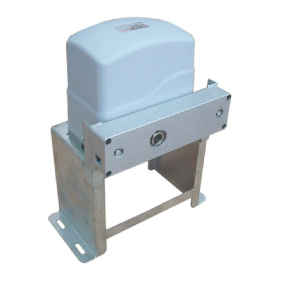
Aleko AC 1500 Manual do utilizador - Página 12
Procurar online ou descarregar pdf Manual do utilizador para Abertura de portões Aleko AC 1500. Aleko AC 1500 16 páginas. Sliding

The RED wire of the motor should be connected into the " 5" terminal.
2. Limit Switches
The YELLOW wire of the limit switches should be connected into the " 8" terminal.
The BLACK wire of the limit switches should be connected into the " 9" terminal.
The RED wire of the limit switches should be connected into the " 10" terminal.
3. Alarm Lamp (Optional)
One wire of the alarm lamp should be connected into the " 6" terminal, another should be connected into the
" 7" terminal.
4. Start Capacitor
The two wires of the start capacitor should be connected into the " 4" terminal and " 5" terminal.
5. Photocell (Optional)
Use a 2-core cable to connect the " + ~" terminal of the photocell' s emitter to the " 13" terminal, the " - ~"
terminal to the " 11" terminal. Also the " + ~" and " - ~" terminals of the photocell' s receiver should be
connected to the " 13" and " 11" terminals in parallel.
Use another 2-core cable to connect the " COM" terminal of the receiver to the " 13" terminal, the " NC"
terminal to the " 12" terminal.
5. Wired Keypad (24VDC)
The RED wire of the wired keypad should be connected into the " 13" terminal.
The BLACK wire of the wired keypad should be connected into the " 11" terminal.
The WHITE wire of the wired keypad should be connected into the " 13" terminal.
The BLUE wire of the wired keypad should be connected into the " 14" terminal.
6. Push Button (Optional)
The push button should be wired to the " 13" and " 14" terminals. The gate operator works alternately by
pushing the button (open-stop-close-stop-open).
Setting Of the Control Board
WARNING: Keep away from the gate during you set the gate opener system in case of the
unexpected gate moving. Carefully adjust the DIP switches to avoid the risk of machine damage and
injury or death. Always ask the help of professional technician /electrician if you have any question.
1. DIP Switches
The DIP switches are used to set the running time of the motor in pedestrian mode, enable/disable auto
close function of the gate operator and fast change the open/close direction which is determined by the
position of the gate operator installed.
11
