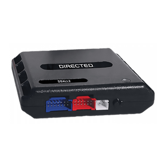
Directed Electronics Xpresskit DBALL Manual de instalação - Página 9
Procurar online ou descarregar pdf Manual de instalação para Acessórios para automóveis Directed Electronics Xpresskit DBALL. Directed Electronics Xpresskit DBALL 14 páginas. Databus all combo bypass module
Também para Directed Electronics Xpresskit DBALL: Manual de instalação (14 páginas)

Platform: DBALL
Firmware: GM5
Installation Type 6
(+) 12v
(-) Ground
2: Green/Black: Bulb Test Passlock1 Only
3: Green/White: (-) Door Status Output*
4: Red/Black: (-) Trunk Status Output*
IGNITION KEY
Bulb
test
* If applicable - see the Function List.
Not required in D2D mode.
The Mobile Integration Systems
(+) Accessory Output
(+) Ignition 2 Output
(+) Brake Input
Parking Lights
(AC) Tach Input
(-) Trunk Status Input*
(-) Door Status Input*
1
8
9
16
Diagnostic connector
OBDII (connector side view)
2: Purple/Yellow: J1850
13:Red: (+) 12v
14:Black: (-) Ground
5: Violet/White: (AC) Tach Output
8: Violet/Green: R. Code
9: Violet/Brown: R. Code
RF Loop Connector
Programming button
LED
Black or
Orange/Black
Bulb test wire coming
Yellow
White or
from black connector
Red/White
at the ignition switch.
BCM
Vehicle CAN Bus Integration System
Ground
(-) Lock Output*
(-) Unlock Output*
(-) Trunk Release Output
(+) Starter Output
(+) Ignition 1 Output
(-) GWR (Status)
(+) Starter
10: Blue/White: (-) GWR (Status) Input
9: Pink: (+) Ignition Input
8: Violet: (+) Starter Input
3: Red/White: (-)
Trunk Release Input
2: Blue: (-) Unlock Input*
1: Green: (-) Lock Input*
(+)12v
RX
(-) Ground
DBALL
TX
P#: XKD2D65
© 2010 Directed Electronics. All rights reserved.
Rev.: 20101103
Page 9
Hood Switch
(+) 12 V Input
