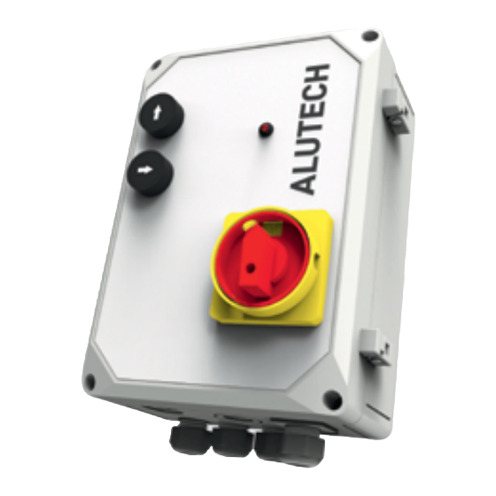
Alutech CUL11 Manual de ligação e funcionamento - Página 11
Procurar online ou descarregar pdf Manual de ligação e funcionamento para Unidade de controlo Alutech CUL11. Alutech CUL11 20 páginas.

OPERATION
1. In order to apply the supply voltage to the control unit module, shift the on-off switch 1
(fig. 1) to I position ('ON' position).
If LED 4 (fig. 1) does not light up or flashes after switching on the control unit,
see section 7 'Faults and recommendations on their elimination' .
2. Make sure / check that hL5 and hL6 LEDs do not light up.
If HL5 and HL6 LEDs or one of them lights up, HL3 LED lights up, then hydraulic
unit valves are not connected or failed.
3. Make sure / check that hL4 LED does not light up, when doors are opened.
If HL4 LED lights up, the door position sensor is triggered (door is closed) or the
jumper position is wrong in J13 connector (fig. 2). If the door position sensor is
not used, the jumper should be connected to the NO contact.
4. Carry out the complete work cycle of the dock leveller (section 6 'Operation').
If the leveller does not start operating, starts operating incorrectly or a fault
occurs during operation (HL2 LED lights up), then stop the operation and go to
section 7 'Faults and recommendations on their elimination' .
5. If the light lamp is connected to the control unit, check whether the lamp is operational.
The lamp switches on when the unit has performed any first action (control button is
pressed, door position sensor is activated) and switches off when the power is turned off.
If the lamp does not light up, then it is not connected or has failed. If the lamp
stops lighting during platform operation, the fault is detected (section 7 'Faults
and recommendations on their elimination').
6. After successful completion of trial cycles, the leveller should return to the initial position.
In order to turn off the power supply, turn the on-off switch 1 (fig. 1) in '0' position
('OFF' position).
Operation logic of the control unit for the electric motor and valves
Power on
Lifting of the dock leveller
Lowering of the dock leveller
Lip extension
Lip retraction
Standby mode after leveller lowering (floating position)
Door position sensor triggering
Stop if a fault is detected (STOP)
OFF — turned off / power off
ON — turned on / power on
6.
OPERATION
Y
ATTENTION! Any person (operator), who operates the loading equipment should be aware of
the safety regulations, existing hazards and risks. The product should not be used by children
or people with physical, sensory or mental disabilities, as well as people with poor experience
and knowledge. Before starting to operate the leveller, make sure that there are no people in
INSTALLATION AND OPERATION MANUAL | CUL11 CONTROL UNIT
Operation
Operation
Motor
Motor
Valve VAL1
Valve VAL1
(MOTOR)
(MOTOR)
OFF
OFF
ON
OFF
OFF
ON
ON
OFF
ON
OFF
OFF
ON
ON
OFF
OFF
OFF
Valve VAL2
Valve VAL2
OFF
ON
OFF
OFF
ON
OFF
OFF
OFF
9
9
