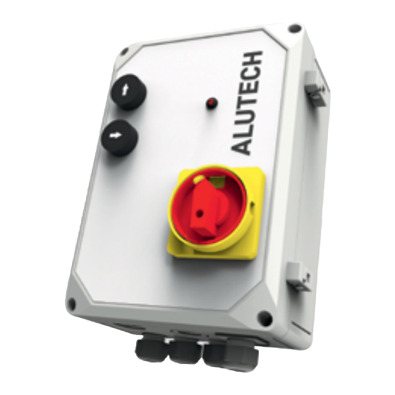
Alutech CUL11 Manual de ligação e funcionamento - Página 13
Procurar online ou descarregar pdf Manual de ligação e funcionamento para Unidade de controlo Alutech CUL11. Alutech CUL11 20 páginas.

STORAGE, TRANSPORTATION AND DISPOSAL
Fault
Fault
After pressing
button, the leveller
does not lift, LED 4 starts
flashing rarely. hL2 LED
lights up
The operation of the
dock leveller stops and
LED 4 flashes rarely. hL2
LED lights up. Light
lamp (if connected)
goes dim
After pressing
button, the leveller
does not lift, the sound
of the motor operation
is heard
After pressing
button, the leveller
does not lift, but the
ramp starts extending
After pressing
button, the dock leveller
does not lift or stops
while moving and
automatically lowers.
hL4 LED lights up
When pressing
button, hL1
or
LED does not light
up, the dock leveller
does not move
Y
ATTENTION! In the normal operation mode, LED 4 (fig. 1) constantly lights up. If after
powering on the unit LED 4 flashes rapidly or rarely, then the control unit operation is blocked.
If the fault occurs during the operation of the dock leveller, the dock leveller movement stops
(no floating position) and control unit operation is blocked. If the light lamp is connected, it
goes dim.
Y
ATTENTION! In order to restore the control unit operation after elimination of the fault, it is
necessary to power on the unit (on-off switch) and briefly press button
In case there is a fault that can't be eliminated with the help of this manual, please contact
the service department. To get more information about it, contact the supplier (dealer or the
company that carried out the installation).
8.
STORAGE, TRANSPORTATION AND DISPOSAL
The product should be stored in its packaging in closed, dry places. Do not expose to atmos-
pheric precipitation and direct sunlight. Storage period—3 years from the date of manufacture.
INSTALLATION AND OPERATION MANUAL | CUL11 CONTROL UNIT
Possible cause
Possible cause
Electric motor
Make sure the electric motor connections are
is not connected
correct. Ensure that all cable wires are connected
in J5 connector of the unit and contacts of the
or connected
incorrectly
electric motor
Overload protection
Set the jumper of J12 connector in the required
in electric motor
current value (section 4 'Electronic module').
is triggered
Check connection of the electric motor
Incorrect
Switch wires for electric motor connection, for
connection
example, at W and V contacts of J5 connector
of electric motor
Correctly connect valves to VAL1 and VAL2
Incorrect
contacts of J8 connector according to the
connection
of valves
operation logic (see table on page 11)
If the door position sensor is connected, check
whether the door is open. Make sure that the
Door position
sensor is connected and operational (check the
state change of sensor LED—LED goes dim or
sensor is triggered
lights up when the sensor is triggered). Check
the setting of jumpers in J9 and J13 connectors
Make sure that control buttons are connected
Control buttons
and operational. Make sure that there is no other
are not connected
fault (check the indication of other LEDs), which
or failed
blocks the control button operation
Recommendations
Recommendations
to lift the leveller.
11
11
