CVS Controls 128PQC Series Manual de instruções - Página 5
Procurar online ou descarregar pdf Manual de instruções para Unidade de controlo CVS Controls 128PQC Series. CVS Controls 128PQC Series 12 páginas.
Replacing Packing and Trim continued,
3. Accessible areas should be cleaned at this
stage, and all necessary maintenance
performed. The actuator and attached trim
parts can be turned over and held by the
valve body.
4. To separate trim and access packing parts
or seal O-rings, first loosen and remove the
valve plug (Key 25) and remove the packing
box washer (Key 27).
5. Remove the packing box (Key 28), O-ring
retainer (Key 18), stem O-ring (Key 19) and
diaphragm casing O-ring (Key 31) off the
stem.
6. Install replacement parts as necessary.
6.1. If a complete packing and trim
assembly is being installed, remove the
assembly from the tube (Key 37),
keeping the web sleeve (Key 39) on the
assembly so the parts remain in place.
Roll the sleeve back as necessary
during installation.
6.2. Continue pushing the assembly onto
the stem until the valve plug and cage
are pushed away from the packing box
washer or wiper ring. Roll the web
sleeve back into place just past the
packing box.
6.3. If installing nitrile/cotton packing, the
packing rings may be lubricated with
silicon based product.
7. Slide the packing box onto the stem until the
packing box, the O-ring (Key 19) and the O-
ring retainer (Key 18) and the diaphragm
casing O-ring (Key 31) are sealed against
the diaphragm casing.
7.1. Ensuring proper positioning of the O-
rings will prevent them from being cut
when other parts are compressed
against them.
7.2. Advance the packing spring washer
(Key 29) , packing spring (Key 21),
second packing spring washer, wiper
ring and packing box washer (Key 27, if
included in the assembly) down onto
the stem.
8. For installation of the packing and trim
assembly, it is necessary to remove the
sleeve, cage puller (Key 40) and cage (Key
23) from the valve plug depending on
individual valve configuration.
9. Fix the valve plug onto the stem, rotating the
plug until the shoulder makes snug contact
with the stem. No further tightening is
necessary.
10. To replace the cage or access the cage O-ring
(Key 22), remove the cage from the body (Key
26) using the cage puller or a wire hook.
Replacement parts can be installed as
necessary.
11. Attach the actuator and trim to the valve body
(Key 26), paying special attention to the cage
O-ring to prevent damage. Thread the four
nuts (Key 32) to the lower diaphragm casing
assembly screws. Nuts must be tightened to
15-foot-pounds (20N
12. Reconnect the input signal tubing to the
actuator connection of the appropriate
diaphragm casing.
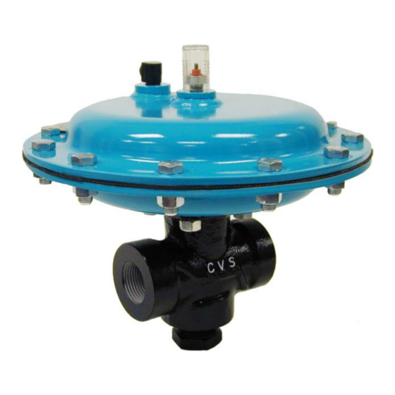
Figure 3: Replacement Packing and Trim
Assemblies for Metal Seated
Constructions
m).
⚫
5