CVS Controls 128PQC Series Manual de instruções - Página 3
Procurar online ou descarregar pdf Manual de instruções para Unidade de controlo CVS Controls 128PQC Series. CVS Controls 128PQC Series 12 páginas.
Installation
Warning:
Service conditions must not exceed the limits
shown on the valve nameplate, or those
outlined in this manual. Consequences could
include bursting of pressure-retaining parts
and uncontrolled process fluid, resulting in
personal injury or property damage. Control
valves should also be protected from external
damages.
Prior to installing the CVS Series 128PQC
Control Valve, perform a complete inspection for
damage, and remove any foreign debris.
Position the valve for desired flow direction. If
angle flow is required, switch the pipe plug to
left-hand connection. (Figure 2)
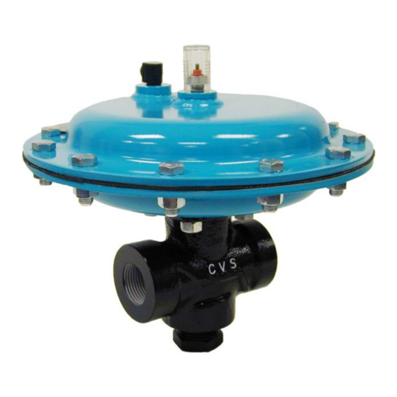
CVS Type 128PQC Control Valve with Fail-Close Action
Figure 2: CVS Type 128PQC Control Valve Typical Constructions
The versatility of this valve allows for installation
in any orientation, with the standard method
being with the actuator above the body.
Standard orientation is best when an angle body
or angle configuration has been specified.
When installing the valve into the line, accepted
piping practices must be used. A three-valve
bypass should be used if continuous operation
is required during inspection or maintenance.
For a fail-close control valve, connect the input
signal line into the 1/4-inch NPT actuator
connection (Figure 2) in the lower diaphragm
case assembly. The input signal pressure line
should be installed in the upper diaphragm case
assembly of a fail-open control valve.
Detail of CVS Type
128PQC Exterior
3