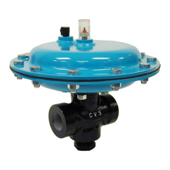
CVS Controls 128PQC Series Manual de instruções - Página 2
Procurar online ou descarregar pdf Manual de instruções para Unidade de controlo CVS Controls 128PQC Series. CVS Controls 128PQC Series 12 páginas.

Description continued,
Any process leakage passing through the
packing is permitted to escape through a leakoff
vent which passes through the packing box and
out the valve body. This prevents any leakage
from passing along the stem into the actuator
and also prevents loading pressure leakage
from the lower diaphragm from reaching the
valve body through the stem.
Table 1: Specifications
Factory-set specifications for your individual CVS 128PQC Control Valve are stamped on the
nameplate, located on the upper diaphragm casing.
End Connection Style
Port Diameters
Maximum Inlet Pressures and
Temperatures**
Maximum Pressure Drops**
Actuator Operating Pressures
Maximum Actuator Casing
Pressure
Shutoff Classifications
Material Temperature
Capabilities
Flow Characteristic
Flow Direction
Maximum Rated Travel
Actuator Diaphragm Effective
Area
Actuator Pressure Connection
Valve Travel Indication
Approximate Weight
** Pressure and temperature restrictions outlined in this guide, along with any applicable code limitation, should not be exceeded
2
CVS Type 128 PQC
In
Metal Seat
CVS Type
mm
128PQC
In
Soft Seat
mm
o
o
o
o
-20
F to +100
F (-29
C to 38
C)
o
o
+150
F (+66
C)
o
o
+180
F (+82
C)
See Table 2
20 psig (1.4 bar) or 35 psig (2.4 bar)
100 psig (6.9 bar)
Metal Seat
Soft Seat
Metal Seat
Soft Seat
Quick opening with 45-degree taper valve plug
Either direction
3/8 inches (10mm)
2
2
33 inches
(213 cm
)
1/4-inch NPT Female
Valve travel is indicated on plastic indicator cover with scale divisions indicated every 25 percent
of travel.
CVS Type 128 PQC
Warning:
The leakoff vent must be kept open at all
times. Flammable or other hazardous fluids
should be vented into an open, well-ventilated
area to prevent fire or explosion.
1-inch NPT Female
1/4, 3/8, 1/2
6.4, 9.5, 12.7
1/4, 3/8, 1/2
6.4, 9.5, 12.7
3600 psig (248 bar)
3550 psig (245 bar)
3520 psig (243 bar)
ASME Class IV ASME/FCI 70-2-1998 – 0.01 percent of
maximum valve capacity using air at a pressure drop of 50 psi
o
(3.4 bar, differential), at 50
F to 125
ASME Class IV ASME/FCI 70-2-1998 – Less than one bubble
per minute (0.15 ml) per minute using air at a pressure drop of
50 psi (3.4 bar, differential) at 50
o
o
o
-20
F to +180
F (-29
C to +82
o
o
o
-20
F to +150
F (-29
C to +55
17 lb (7.7 kg)
o
o
o
F (10
C to 52
C)
o
o
o
o
F to 125
F (10
C to 52
C)
o
C)
o
C)
