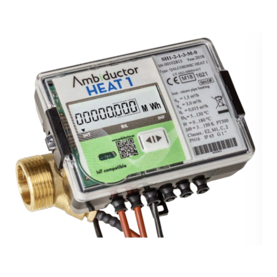
Ambiductor HEAT 1 Manual de instruções de funcionamento e montagem - Página 3
Procurar online ou descarregar pdf Manual de instruções de funcionamento e montagem para Instrumentos de medição Ambiductor HEAT 1. Ambiductor HEAT 1 20 páginas.

Installation instructions
Basic requirements
Heat meters are intended for installation in heating or com-
bined heating and cooling systems.
Before installing the device:
1.
Make sure all parts listed in the documentation are avail-
able
2.
Check for any visible mechanical defects
3.
Check if there are valid labels by the manufacturer and
the certification authority
Only qualified personnel may install the equipment, and must
comply with the requirements set forth in this document in the
technical documentation for other system components.
It is prohibited to mount signal cables less than 5 cm from
power cables and cables to other devices.
It is forbidden to change the length of any cable.
Mounting
Mounting of flow sensors
Sizes and fittings of the flow sensor are available in Dimen-
sions and connections.
Up to DN50 there are no requirements for straight pipes for
installation. From DN65, 5xDN applies upstream, 3xDN down-
stream. Avoid flow meter installation close to pumps that can
cause cavitation.
Flow sensors can be mounted both vertically and horizontally
in pipelines. Vertical mounting of the flow sensor is permitted
only if the flow direction in the pipeline is upwards.
The direction of the flow sensor (indicated by the arrow below
the flow sensor) must match the flow direction in the pipe.
The connection gasket must match the pipe diameter. During
installation, the gasket must be precisely centered with the
center of the pipe cross section to avoid sticking gaskets inside
the pipe.
NOTE! Flow sensors must be mounted between shut-off valves
to enable validation/calibration and simplify service.
Mounting of temperature sensors
Temperature sensors are mounted perpendicular to the pipe or
inclined at a 45° angle to the liquid flow direction so that the
sensor element has been inserted close to the center of the
pipe (see Marking and sealing).
In G20 / G¾ "and G25 / G1 meters, a temperature sensor is
pre-mounted in the flow sensor.
Mounting of energy calculator
Energy calculators can be installed in heated premises, ambi-
ent temperature should be max +55 ° C. It should not be
exposed to direct sunlight.
For liquids outside +10 ... 90 °, the calculator should NOT be
mounted on the flow sensor.
The calculator can easily be mounted on the wall thanks to
DIN rail mounting.
The cable between the calculator and the flow sensor is nor-
mally 1.2m (can be ordered 2.5 and 5.0m).
Ambiductor AB reserves the right to make changes without prior notice. Reprinting or copying this publication without permission is prosecuted.
Mounting on standard DIN rail
Mounting on adapter plate according to figure 8 in EN1434-2:
2007 for wall mounting of calculator can be used (if the open-
ing in the wall is too large for the calculator)
Direct mounting on the ultrasonic flow sensor rotatable for ev-
ery 90 ° (only allowed when the temperature of the liquid does
not exceed 90 ° C):
Important: It is forbidden to attach the calculator di-
rectly to a wall with a risk of condensation or tempera-
tures below +5 ° C. Then it is recommended to attach
the calculator with an air gap of at least 5 cm.
3
