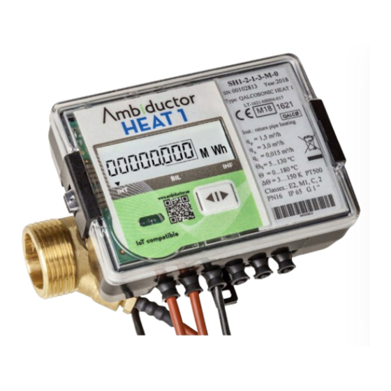
Ambiductor HEAT 1 Manual de instruções de funcionamento e montagem - Página 4
Procurar online ou descarregar pdf Manual de instruções de funcionamento e montagem para Instrumentos de medição Ambiductor HEAT 1. Ambiductor HEAT 1 20 páginas.

Jumpers J setting
The connector J is located in the integrator between the con-
nection terminals of the temperature sensors and the pulses
/ outputs (see below). By using or not using jumpers on this
connector, one can enter / exit test mode and select pulse
inputs or outputs:
Jumpers 1-5
Jumper NOTE con-
nected (open)
User mode
Pulse 1 - OUTPUT active
(terminals 52,53)
Pulse 2 - OUTPUT active
(terminals 50,51)
Checking installation & configuration
After installing the heat meter, flow the fluid through the flow
sensor. Measured values should be displayed on the display
if the heat meter (calculator, flow and temperature sensor) is
correctly installed. If the measured values are not displayed
correctly, it is necessary to check the installation.
Sealing after installation
If the meter is to be used for billing, it must be sealed so
that, after installation, it cannot be disassembled, moved or
changed without obvious damage to the meter or seal.
See section "Labeling and sealing" later in this documentation
for more information.
Electrical installation
Calculator's terminals
Terminal
Connection
5
Hot temp sensor (T1)
6
Hot temp sensor (T1)
7
Cold temp sensor (T2)
8
Cold temp sensor (T2)
50
Pulsin/output 2 - GND
51
Pulsin/output 2 (volume in test mode)
52
Pulsin/output 1 - GND
53
Pulsin/output 1 (energy in test mode)
Extra terminals
Terminal
Connection
24
M-bus (on M-bus-module)
25
M-bus (on M-bus-module)
20
CL+ (on CL-module)
21
CL- (on CL-module)
Ambiductor AB reserves the right to make changes without prior notice. Reprinting or copying this publication without permission is prosecuted.
Communication card
Jumper connected
(closed contact)
Verification/test/service
mode
Pulse 1 - INPUT active
(terminals 52,53)
Pulse 2 - INPUT active
(terminals 50,51)
With factory mounted sensors, it is forbidden to split, shorten
or extend the cables. If screw terminals are available on the
calculator, cables, during commissioning, may temporarily be
disconnected from the terminals and reconnected.
If sensors other than those supplied with the meter are used,
type-approved and matching pairs of temperature sensors with
two-wire connection must be used.
Before installation, check that the temperature sensors are
paired.
Using a pliers, remove the protective balls from the holes 1
and 2 of the cable entry on the left side of the calculator.
Pull the cable to the flow temperature sensor T1 through the
hole 1 and the cable to the return temperature sensor T2
through the hole 2.
Use two-wire connection for the temperature sensors (see
electrical diagram above).
tion modules
In the lower right corner of the calculator, communication
modules can be mounted and connected. The module is fas-
tened with two screws.
Using a pliers, remove the protective ball from a non-used
cable entry into the calculator. Pull the cable through the hole
and attach as shown below.
Connect a cable to the module according to the instructions for
each module.
24V module and 230V unit are available for external power
supply. See separate documentation.
4
Temperature sensor connection
Connection of the customer's tempera-
ture sensor
Installation of additional communica-
