CO2 Meter RAD-0501A Инструкция по эксплуатации
Просмотреть онлайн или скачать pdf Инструкция по эксплуатации для Контроллер CO2 Meter RAD-0501A. CO2 Meter RAD-0501A 4 страницы. Co2 controller
CO2 Controller Operating Instructions
Models: RAD-0501, RAD-0501A
1. Product Description
RAD-0501 Greenhouse Mode: Controls CO2 generator or regulator to
increase CO2 levels during daylight for plant growth.
RAD-0501A Ventilation Mode: Controls an exhaust fan when CO2 levels
are higher than recommended maximum for your application.
Main Features (Both Models):
1.
Accurately measures CO2 concentrations up to 2,000ppm
2.
Built-in temperature (°C or °F) measurement
3.
Automatic altitude compensation via built-in barometric sensor
4.
Relay-controlled outlet regulated by long-lasting CO2 sensor.
2. Contents & Description
1.
CO2 Controller
2.
Wall panel holder (1)
3.
Screws (2)
4.
Drywall anchors (2)
5.
User Manual
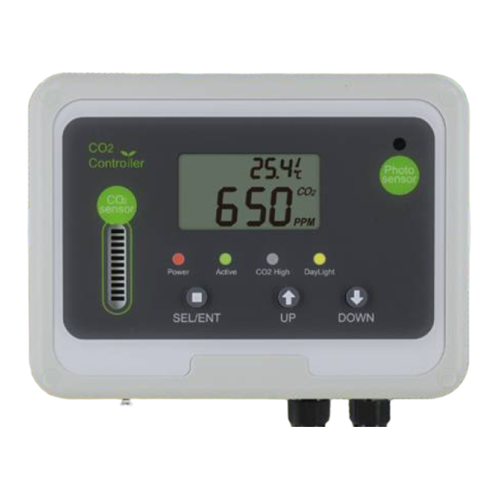
A. LCD Display
B. Photo Sensor (monitor light or darkness)
C. Red LED (power on indicator)
D. Green LED (lights when CO2 concentration is below SetPoint)
E. Red LED (lights when CO2 concentration above SetPoint)
F. Yellow LED (verifies photo sensor is working)
G. Down Button
H. Up Button
I. SEL / ENT Button
J. Unit power and relay-controlled power "piggyback" plug
K. Panel Holder
L. CO2 sensor
M. Tube fitting for bottled gas calibration
N. 4-20mA Linear Analog Output for CO2 level
3. Caring for the Product
To get the most out of this product, please observe the following
1.
Repair - Do not attempt to repair the product or modify the circuitry
by yourself. Contact CO2Meter.com if the product needs servicing,
including the replacement or calibration of the sensor.
2.
Cleaning - Disconnect the power before cleaning. Use a damp cloth.
Do not use liquid cleaning agents such as benzene, thinner or
aerosols, as these will damage the device.
4. Connection Diagram
Note: In Greenhouse Mode piggyback plug controls CO2 regulator or generator.
In Ventilation Mode piggyback plug controls an exhaust fan.
5. How it Works
1.
The Red LED (power) is on when the power is supplied.
2.
Greenhouse Mode: The Yellow LED is lit when the photo sensor is
active. The photo sensor is used to detect the presence or absence
of light. When light is present, and CO2 levels are lower than the
Target CO2 level, the Green LED is on and power will be supplied to
the piggyback plug. When CO2 levels reach the Target level, the
Green LED will go off, the Red LED will turn on, and power will be cut
to the piggyback plug. In darkness, the piggyback plug is not
powered regardless of the CO2 level.
3.
Ventilation Mode: If CO2 levels are higher than the Target level, the
Green LED will turn on and power will be supplied to the piggyback
plug. When CO2 levels decrease below the target, the Green LED
will go off and power will be cut to the piggyback plug. The photo
sensor is disabled.
6. LCD Display
Symbol
CO2 Level
Temperature
Barometric
Pressure
Restore Factory
RCFS
Settings
CAL
Calibration
Set CO2 Value
TARGET
Relay is Activated
Greenhouse Mode
Ventilation Mode
1
Meaning
Description
CO2 Concentration in ppm
(Parts Per Million)
Displays current temperature.
Switch °C / °F with UP key
Displays air pressure. Switch
inHg / mmHg with DOWN key
Restore factory default settings
and delete all custom settings
Fresh air or known CO2 level
gas calibration in process
CO2 level when relay is turned
on or off depending on mode
When the relay is powered ON
will be shown on the LCD
Relay on below CO2 set-point,
(default)
photo sensor enabled
Relay on above CO2 set-point,
photo sensor disabled