Ekinex EK-BG1-TP Руководство
Просмотреть онлайн или скачать pdf Руководство для Шлюз Ekinex EK-BG1-TP. Ekinex EK-BG1-TP 3 страницы. Knx - dali gateway

KNX - Dali Gateway
Code: EK-BG1-TP
Description
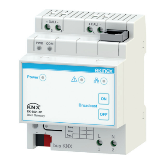
The ekinex EK-BG1-TP gateway establishes the bidirec-
tional data connection between a DALI system and a KNX
bus system. The gateway allows you to control lighting
devices equipped with a standard DALI interface and
different light sources (such as fluorescent lamps, high
intensity discharge lamps and LEDs) by means of KNX
devices (such as buttons, motion and presence sensors
or touchpanels). The device has an integrated KNX bus
communication module and is designed for mounting on a
35 mm profile DIN rail. The device is powered at 230 VAC
and supplies SELV power to the DALI bus.
DALI
DALI (Digital Addressable Lighting Interface) is an open
and interoperable worldwide standard dedicated to ligh-
ting applications and specified by the IEC (International
Electrotechnical Commission). The DALI protocol is inclu-
ded in the technical standard IEC 62386 Digital addressa-
ble lighting interface.
For further information: www.dali-ag.org.
Main features
• Plastic case
• Version for mounting on 35 mm profile DIN rail (accor-
ding to EN 60715)
• Degree of protection IP20 (according to EN 60529)
• Security class II
• Weight 200 g
• 4 UM modular device (1 UM = 18 mm)
• Dimensions 72 x 95 x 60 mm (LxHxP)
Datasheet STEKBG1TP_EN
1
Technical data:
Connections:
• Power supply (230 V AC)
• KNX bus
• DALI bus
• Ethernet
DALI System:
• Transmission medium: unshielded cable
• Topology: linear, star or mixed
• Current consumption: max 250 mA
• DALI voltage: 9.5 V ... 22.5 V (typical 16 V)
• Max cable length: 300 m (section 1.5 mm²)
• Baud rate: 1200 bps
• Max number of DALI devices: 64
• Max number of DALI groups: 16
• Max number of DALI scenes: 16
Environmental conditions:
• Temperature range: -5 ... + 45°C
• Relative humidity: 95% non condensing
Operating, signaling and connecting elements
The appliance is equipped with:
• One terminal for the KNX bus line connection (1)
• Two terminals for the power supply connection (4)
• Two 2-pole terminals for the DALI bus connection(5)
• One RJ45 connector (6)
• One KNX programming button (2) with associated LED
(3)
• Three signaling LEDs (9, 10, 11)
• Two membrane keys (12)
5
7
8
9
3
1
2
Mounting
The device has degree of protection IP20 and is there-
fore suitable for use in dry indoor environments. The en-
closure is designed to be mounted on a DIN profile rail
according to EN 60715 inside switchboards or electrical
distribution cabinets. The device must be mounted in a
vertical position; correct positioning is with the terminal for
the KNX bus is located at the bottom.
i
Note. When installing in switchboards and distribution cabinets,
the necessary ventilation must be ensured in order to maintain
the temperature within the operating range allowed for the ap-
pliance.
6
11
10
12
4
