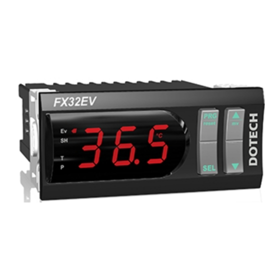
DOTECH FX32EV Руководство - Страница 3
Просмотреть онлайн или скачать pdf Руководство для Блок управления DOTECH FX32EV. DOTECH FX32EV 4 страницы. Electronic expansion valve control unit

Setting 1 Group Table
NO.
DESCRIPTION
002
Bias
003
Proportional Band
004
Integral Time
005
Derivative Time
006
Low Superheat Alarm
007
High Superheat Alarm
008
Pressure Lower Limit Alarm (LOP)
009
Pressure Upper Limit Alarm (MOP)
013
Expansion Valve Control Upper Limit
014
Expansion Valve Control Lower Limit
015
No Response Control Range
016
Operation Delay Time
019
Expansion Valve Compulsory Control
* Bias : Initial control output value of expansion valve (expansion valve open ratio at point which setting superheat value is equal to current superheat value).
* Proportional Band : Initial control range value of expansion valve (when setting superheat is 6.0K and proportional band is 5.0K, it can be controlled within range of
3.5K(0%) ~ 8.5K(100%)) - Please increase proportional band if width of vibration of superheat value is large.
* Integral Time : It controls open ratio of expansion valve by accumulating error each integral time - increase integral time if cycle of vibration of superheat value is short.
* Derivative Time : It is used in circumstance where It needs instant response. Generally setting value is '0'.
* Low Superheat Alarm : Input low superheat alarm value. It closes valve until become control lower limit value of expansion valve if superheat is lower than low superheat alarm value.
* High Superheat Alarm : Input high superheat alarm value. It opens valve until become control upper limit value of expansion valve if superheat is higher than high superheat alarm value.
* Pressure Lower Limit Alarm : It opens expansion valve to 100% if suction pressure is lower than pressure lower limit alarm.
* Pressure Higher Limit Alarm : It closes expansion valve to 0% if suction pressure is higher than pressure upper limit alarm.
* Expansion Valve Control Upper Limit : Setup maximum open ratio of expansion valve (but, It opens valve to 100% regardless of upper limit value if pressure lower limit alarm occurs.)
* Expansion Valve Control Lower Limit : Setup minimum open ratio of expansion valve (but, It closes valve to 0% regardless of lower limit value if pressure upper limit alarm occurs.)
* No Response Control Range : Keep open ratio of expansion valve if superheat is controlled within setting superheat +/- (no response control range).
* Operation Delay Time : Start to control after setup delay time if there is operation start input.
* Expansion Valve Manual Control : It is used when user compulsorily controls expansion valve at open ratio which is set by user. compulsory control function is not used if setup is OFF.
Setting 2 Group Table
NO.
DESCRIPTION
300
Lock Selection
Refrigerant
301
302
Upper Limit Input Range of Pressure Sensor
303
Lower Limit Input Range of Pressure Sensor
304
Pressure Sensor Compensation
307
Temperature Sensor Compensation
308
Minimum Valve ON Time
309
Expansion Valve Control Cycle
Output when Sensor Error
310
311
Expansion Valve Control Slope
312
Display Mode
313
Remote Operation Function
Analogue Output Function (-A1 model)
315
318
Communication ID (-R4 model)
319
Communication Speed (-R4 model)
* Minimum Valve ON Time : It makes compulsorily valve ON during setup time if it needs control for period which is shorter than setup time when controlling valve ON/OFF.
This function do not work when setup is OFF.
* Expansion Valve Control Cycle : Setup control cycle of ON/OFF type expansion valve. Setup 6 sec. for AKV series of Danfoss.
* Output when Sensor Error : Setup output ratio of expansion valve to output compulsorily when temperature or pressure sensor error occurs.
* Expansion Valve Control Slope : Input control various value of expansion valve to increase or decrease per second. It is used when rapid control is needed.
* Display Mode : Display in order Superheat --> Temperature --> suction pressure when rotation mode.
CODE
UNIT
B I R
%
D F R
'C
I R T
SEC
D R T
SEC
L S H
K
H S H
K
L O P
bar
H O P
bar
H I 0
%
L O 0
%
D B N
K
R D T
SEC
M A 0
%
CODE
UNIT
:
Lock clear
L O C
Setting 1, 2 group Lock
:
2 2 : R22
I 3 4 : R134A
R T Y
4 I 0 : R410A
7 I 7 : R717
S H
bar
S L
bar
P O F
bar
T O F
'C
M O T
sec
P R T
sec
S F O
%
J E K
%
D I S
0:Rotation, 1:Superheat, 2:Temperature, 3:Suction pressure
R M T
0:Always operation, 1:Remote operation, 2:Communication operation
A O M
0:Pressure transmission output, 1:Control output (for 4~20mA type valve control)
I D
1 ~ 32
B D R
48 : 4800BPS, 96 : 9600BPS, I92 : 19200BPS, 384 : 38400BPS
Compulsory parameter for operation
STEP
MIN.
1
0
0.1
0.5
1
0
1
0
0.1
-9.9
0.1
-9.9
0.1
-1.0
0.1
-1.0
1
0
1
0
0.1
0
1
0
1
0
STEP
MIN.
Setting 1 group Lock
:
Setting 1,2 group and superheat setup Lock
:
: R404A
4 0 7 : R407C
4 0 4
: R23
2 3
1
-1
1
-1
0.1
-9.9
0.1
-19.9
0.1
O F F
1
O F F
1
0
1
O F F
Second degree parameter for optimum operation
MAX.
DEFAULT
USER SETUP
100
50
99.9
5.0
999
30
999
0
99.9
0.0
99.9
19.0
99.9
0.5
99.9
8.0
100
100
0
0
5.0
0.1
300
5
100
oFF
MAX.
DEFAULT
USER SETUP
2 2
99
9
99
-1
9.9
0.0
19.9
0.0
9.9
O F F
60
6
100
0
100
5
0
1
0
1
96
