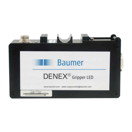
Baumer DENEX Gripper LED Руководство пользователя - Страница 14
Просмотреть онлайн или скачать pdf Руководство пользователя для Аксессуары Baumer DENEX Gripper LED. Baumer DENEX Gripper LED 24 страницы.

7
LED INDICATORS
There are four LED's that are placed close to the connector for checking the operation of
the sensor,
POWER (GREEN)
LED OFF (RED)
OUTPUT (ORANGE)
STATUS (YELLOW)
7.1
The POWER-LED
The green POWER-LED indicates that the sensor has power and should be operating.
Never mount or adjust the sensor when this LED is on!
7.2
The "LED OFF"- LED
The "LED OFF"-LED is an indication that the light emitting diode is off. The LED could be
shut off for the following reasons:
• The LED-power level has changed in an uncontrolled way (electronic problem inside
sensor)
• The LED-power level is too low to ensure a good operation
If the LED-levels are outside of the allowed limits, the sensor must be sent for repair.
7.3
The OUTPUT- LED
The OUTPUT-LED is active when the output stage is active (set). The LED will flash for
every output pulse that is sent. The output pulse width can be set with the DIP-switches,
see chapter 6.4, "DIP-Switch Settings". By watching this LED, it is fairly easy to see that
the sensor is giving the correct amount of pulses.
7.4
The STATUS- LED
see chapter 6, "SOFTWARE FUNCTIONS".
User Manual DENEX Gripper LED
Version 2013-02, V1.4
Figure 7.1 Position of LED:s.
14/24
www.baumer.com
Baumer Electric AG
Frauenfeld, Switzerland
