Atlas F6-MF Руководство пользователя - Страница 7
Просмотреть онлайн или скачать pdf Руководство пользователя для Усилитель Atlas F6-MF. Atlas F6-MF 16 страниц. Multi-impedance modular amplifier
Также для Atlas F6-MF: Руководство пользователя (3 страниц)

Owner's Manual
Front Panel
1. System LED Indicators
Power
W hen AC Mains power is applied to the F6-MF and the AC Mains Power Switch is in the "On" position, this LED will
illuminate Blue indicating the F6-MF is ready for use.
Temp
T his LED represents the temperature condition of the Mainframe. The LED will illuminate Yellow if any of the FM250
amplifier channels reaches 10% of their Thermal Protect shut off and the fan cooling system is at its maximum cooling
capability. Also refer to the Protect LED below.
Standby
I f the Standby LED is illuminating Orange, it means the F6-MF is in Energy Save Mode. The F6-MF can be turned on
via three methods; Power Switch, DC Voltage, or Contact Closure. Note: The F6-MF is shipped with a shunt across
the CC contacts to activate the amp from Standby Mode. This is to be used when remote activation is not required.
If the Standby LED is not illuminating, the Front Panel Blue LED Power LED will be illuminated and, the FM Module's
Ready LEDs (Green) will be on. This means the amplifier is ready to use. If not, check the AC Mains and power switch.
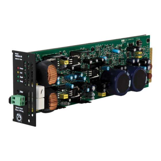
2. Module LED Status Indicators for Each Channel
Ready
T his LED will illuminate Green when an FM250 power module is installed on the appropriate channel and the F6-MF is
turned on.
Signal
T he channel Signal LED will illuminate Green when the FM250 amplifier output signal produces a minimum 1 Watt
output.
Limit
T he Limit LED will illuminate Yellow under load conditions. If the FM250 function switch is set to Limit then the LED
acts as a maximum level indicator. If the FM250 channel Limit function is off, the LED reacts as a Clip indicator. Also,
under Low Impedance loads, this LED serves as a current Limit indictor.
Protect
T he Protect LED will illuminate Red during one the following conditions. No output will occur while this LED is
illuminated. It will reset itself after the condition has been corrected.
1) Shorted speaker output.
2) Thermal Shut Off. The Temp F6-MF TEMP LED will also be illuminated.
3) Current Overdrive. If the amplifier channel is driving too low of a speaker load.
3. Channel Level Controls
T here are six detented level controls, one for each of the F6-MF's six FM250 channel card slots. When any of the potentiometers
is turned down (left or FCC (Fully Counter Clockwise)), no signal will come out of the corresponding amp channel. When the
potentiometer is turned up (right to the eighth detent or FC (Fully Clockwise)), the amp will be set for maximum level.
4. Air Exhaust
The F6-MF has fan assist cooling and draws cool air in from the rear of the amp and exhausts the hot air out of the front panel.
Multi-Impedance Modular Amplifier
2
1
3
1601 Jack McKay Blvd. • Ennis, Texas 75119 U.S.A.
Telephone: 800.876.3333 • Fax: 800.765.3435
– 7 –
Specifications are subject to change without notice.
F6-MF
4
AtlasSound.com
