Advanced Radio Smart Switch Краткое руководство по эксплуатации - Страница 5
Просмотреть онлайн или скачать pdf Краткое руководство по эксплуатации для Панель управления Advanced Radio Smart Switch. Advanced Radio Smart Switch 15 страниц.

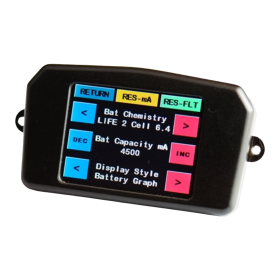
Mounting the Smart Display
There are 2 options of mounting the Smart display.
NOTE: Which ever method of mounting you choose, ensure the purple cable that comes
out of the Smart Display is not crushed in anyway. Doing so will reduce the longevity of
the cables.
Option 1. Using the remaining pieces of 3M clear tape, we can mount the back of the screen
to a surface.
tion. AVOID MOUNTING IN HIGH VIBRATION AREAS. VIBRATION DAMAGE IS NOT COV-
ERED UNDER WARRANTY.
surface that it is being mounted. Place a piece of 3M tape each side of the purple cable.
Trimming the tape as necessary. Remove the clear film and place the tape on the back of the
screen then press the screen into place.
THE SCREEN WITH FORCE AS IT MAY BREAK.
ensure it is secure
Option 2. For hard mounting, the screen case has 2 little tabs with eyelet holes in them. If you are
mounting the screen in a scale cockpit, or in a non vibration model. (e.g Turbine) these holes can be
used to affix the Smart Display.
Simply place the Smart Display where you wish to mount it. Holding it in place, make a dot using a
pen or pencil in each eyelet hole. Removing the screen, drill a hole where you placed the dots.
Now simply screw the Smart Display in place.
NOTE: Hard mounting the Smart Display provides little to no protection against vibration.
Use this method if you are using a non vibration model or only where there is little to no
vibration. AVOID MOUNTING IN HIGH VIBRATION AREAS. VIBRATION DAMAGE IS NOT
COVERED UNDER WARRANTY.
5
NOTE: This is a semi hard mount, and will provide a good resistance to vibra-
As mentioned above, clean both the back of the smart screen and
IMPORTANT: DO NOT APPLY FORCE DIRECTLY ON TO
Press on the black case around the screen to
