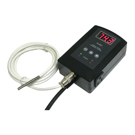
Auber Instruments TD120-W Руководство по эксплуатации - Страница 4
Просмотреть онлайн или скачать pdf Руководство по эксплуатации для Контроллер температуры Auber Instruments TD120-W. Auber Instruments TD120-W 4 страницы. Wireless temperature controller
Также для Auber Instruments TD120-W: Дополнительное руководство (2 страниц)

AUBER INSTRUMENTS
2. There are two Set Points -- CSP and HSP. Each Set Point has its
own output relay, Cooling Relay and Heating Relay. Each Set Point
has a control differential value, CdF or HdF.
3. In the Reverse Logic mode, user can choose to use either the
Cooling Relay (output socket on the left) or the Heating Relay (output
socket on the right) to drive an external load.
4. In the Reverse Logic mode, the relay will be energized when the
probe reading is within the temperature range set by CSP (75° F) and
HSP (32° F) as well as their differential bands CdF and HdF.
Note 8. rST is the factory reset parameter. Choose "Yes" to reset all
the parameters back to factory settings.
Note 9. PSd is the device access password (only available to TD120-
W model). This parameter is used to lock the access to parameter
settings on Aubersmart App.
7. How to install the sensor to the unit.
The connector of sensor contains a slot for fitting pin connection. It also
has a spring lock to prevent disconnections from accidental pulling on
the cable. To install the sensor to the controller: 1) identify the key on
the male connector (Figure 5, a) and the notch on the female connector
(Figure 5, b); 2) hold the tail of the female connector, align the notch
and the key, and push the female connector forward (Figure 5, c). To
remove the connector, hold the spring-loaded collar on the female
connector and pull it back. Please see Figure 6.
2019.08
(a)
(b)
Copyright 2007-2019, Auber Instruments All Rights Reserved.
No part of this manual shall be copied, reproduced, or transmitted in any way
without the prior, written consent of Auber Instruments. Auber Instruments
retains the exclusive rights to all information included in this document.
WWW.AUBERINS.COM
Figure 5. Install the sensor.
Figure 6. Remove the sensor.
Auber Instruments Inc.
5755 North Point Parkway, Suite 99,
Alpharetta, GA 30022
www.auberins.com
E-mail: [email protected] Tel: 770-569-8420
(c)
P4/4
