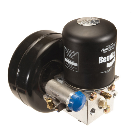
BENDIX AD-IS - Руководство - Страница 4
Просмотреть онлайн или скачать pdf Руководство для Осушитель BENDIX AD-IS -. BENDIX AD-IS - 17 страниц. Air dryer and reservoir system
Также для BENDIX AD-IS -: Брошюра (2 страниц), Служебные данные (15 страниц)

- 1. Air Dryer/Reservoir System Charge Cycle
- 2. Air Dryer/Reservoir System Purge Cycle
- 3. Charge Cycle
- 4. Purge Cycle
- 5. Preventive Maintenance
- 6. Operation & Leakage Tests
- 7. Pressure Protection Valve Locations
- 8. Testing
- 9. Braking System Protection & Inspection
- 10. Temporary Air Dryer/Reservoir System Bypass
- 11. Delivery Check Valve Cleaning Procedure
- 12. Cleaning and Inspection
- 13. Troubleshooting
of the contaminants to condense and drop to the bottom of
the air dryer and reservoir system purge valve assembly,
ready to be expelled at the next purge cycle. The air then
flows into the desiccant cartridge, where it flows through an
oil separator which removes liquid oil and solid contaminants.
Air then flows into the desiccant drying bed and becomes
progressively drier as water vapor adheres to the desiccant
material in a process known as "ADSORPTION."
Dry air exits the desiccant cartridge through the center of
the base assembly. The air then flows to the delivery check
valve and also through an orifice into the purge reservoir.
The delivery check valve opens, supplying air to the pressure
protection valves (A) through (D) simultaneously, the safety
valve, and also to the reservoir port of the attached governor.
The purge reservoir fills, storing air that will be used to
reactivate the desiccant during the purge cycle. This air is
available to supply downstream components during the
charge mode.
When the air pressure reaches approximately 106 psi, the
four pressure protection valves will open and air will be
supplied to the primary reservoir, secondary reservoir and
accessories. If the pressure protection valves are preset to
different values the valves will open in order of lowest setting
to highest setting when charging a flat system.
The air dryer and reservoir system will remain in the charge
cycle until the air brake system pressure builds to the
governor cut-out setting of approximately 130 p.s.i.
PURGE CYCLE
(Refer to Figure 3.)
When air brake system pressure reaches the cut-out setting
of the governor, the governor unloads the compressor and
the purge cycle of the air dryer and reservoir system begins.
The governor unloads the compressor by allowing air
pressure to fill the line leading to the compressor unloader
mechanism - causing the delivery of compressed air to
®
the AD-IS
air dryer and reservoir system to be suspended.
Similarly, the governor also supplies air pressure to the
®
AD-IS
air dryer and reservoir system purge control channel.
The AD-IS
®
air dryer and reservoir system purge piston
moves down in response to this air pressure, causing the
purge valve to open to the atmosphere and the turbo cut-off
valve to close off the supply of air from the compressor (this
will be further discussed in the Turbo Cut-off Feature
section). Water and contaminants which have collected in
the purge valve base are expelled immediately when the
purge valve opens. Also, air which was flowing through the
desiccant cartridge changes direction and begins to flow
toward the open purge valve. Oil and solid contaminants
collected by the oil separator are removed by air flowing
from the purge reservoir through the desiccant drying bed
to the open purge valve.
4
The initial purge and desiccant cartridge decompression
lasts only a few seconds and is evidenced by an audible
burst of air at the AD-IS
exhaust.
The actual reactivation of the desiccant drying bed begins
as dry air from the purge reservoir flows through the purge
orifice into the desiccant bed. Pressurized air from the
purge reservoir expands after passing through the purge
orifice; its pressure is lowered and its volume increased.
The flow of dry air through the drying bed reactivates the
desiccant material by removing the water vapor adhering to
it. Approximately 30 seconds are required for the entire
contents of the purge reservoir of a standard AD-IS
and reservoir system to flow through the desiccant drying
bed.
The delivery check valve assembly prevents air pressure in
the brake system from returning to the air dryer and reservoir
system during the purge cycle. After the purge cycle is
complete, the air dryer and reservoir system is ready for
the next charge cycle to begin.
TURBO CUT-OFF FEATURE
The primary function of the turbo cut-off valve is to prevent
loss of engine turbocharger air pressure through the
®
AD-IS
air dryer and reservoir system when the dryer is in
the unloaded mode.
At the onset of the purge cycle, the downward travel of the
purge piston is stopped when the turbo cut-off valve (tapered
portion of purge piston) contacts its mating metal seat in
the purge valve housing. With the turbo cut-off valve seated
(closed position), air in the compressor discharge line and
®
AD-IS
air dryer and reservoir system inlet port cannot enter
the air dryer and reservoir system. In this manner the turbo
cut-off effectively maintains turbo charger boost pressure
to the engine.
PREVENTIVE MAINTENANCE
Important: Review the warranty policy before performing
any intrusive maintenance procedures. An extended
warranty may be voided if intrusive maintenance is performed
during this period. Purge valve maintenance is permissible
during the warranty period only when using a genuine Bendix
purge valve kit.
Because no two vehicles operate under identical conditions,
maintenance and maintenance intervals will vary.
Experience is a valuable guide in determining the best
maintenance interval for any one particular operation.
Every 900 operating hours, or 25,000 miles or three (3)
months:
1. Check for moisture in the air brake system by opening
reservoir drain valves and checking for presence of
water. If moisture is present, the desiccant cartridge
®
air dryer and reservoir system
®
(Refer to Figure 3.)
air dryer
