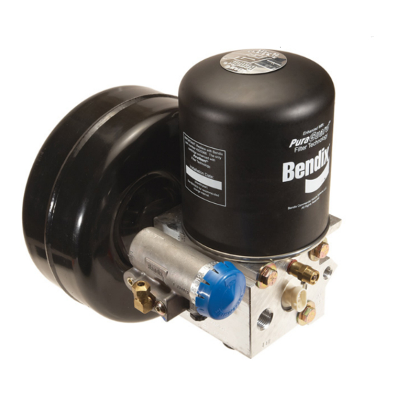
BENDIX AD-IS - Руководство - Страница 6
Просмотреть онлайн или скачать pdf Руководство для Осушитель BENDIX AD-IS -. BENDIX AD-IS - 17 страниц. Air dryer and reservoir system
Также для BENDIX AD-IS -: Брошюра (2 страниц), Служебные данные (15 страниц)

- 1. Air Dryer/Reservoir System Charge Cycle
- 2. Air Dryer/Reservoir System Purge Cycle
- 3. Charge Cycle
- 4. Purge Cycle
- 5. Preventive Maintenance
- 6. Operation & Leakage Tests
- 7. Pressure Protection Valve Locations
- 8. Testing
- 9. Braking System Protection & Inspection
- 10. Temporary Air Dryer/Reservoir System Bypass
- 11. Delivery Check Valve Cleaning Procedure
- 12. Cleaning and Inspection
- 13. Troubleshooting
A. Electric Power to the Dryer
With the ignition or engine kill switch in the RUN
position, check for voltage to the heater and
thermostat assembly using a voltmeter or testlight.
Unplug the electrical connector at the air dryer and
reservoir system and place the test leads on each of
the connections of the female connector on the
vehicle power lead. If there is no voltage, look for a
blown fuse, broken wires, or corrosion in the vehicle
wiring harness. Check to see if a good ground path
exists.
B. Thermostat and Heater Operation
Note: These tests are not possible except in cold
weather operation.
Turn off the ignition switch and cool the thermostat and
heater assembly to below 40 degrees Fahrenheit. Using
an ohmmeter, check the resistance between the
electrical pins in the air dryer and reservoir system
connector half. The resistance should be 1.5 to 3.0
ohms for the 12 volt heater assembly and 6.0 to 9.0
ohms for the 24 volt heater assembly.
Warm the thermostat and heater assembly to
approximately 90 degrees Fahrenheit and again check
the resistance. The resistance should exceed 1000
ohms. If the resistance values obtained are within the
stated limits, the thermostat and heater assembly is
operating properly. If the resistance values obtained are
outside the stated limits, replace the heater and
thermostat assembly.
6. Pressure Protection Valves. Observe the pressure
gauges of the vehicle as system pressure builds from
zero. The primary or secondary gauge should rise until
it reaches approximately 106 p.s.i. (±6 p.s.i.), then level
off (or a momentary slight fall) as the next pressure
protection valve opens supplying its reservoir. When
that pressure gauge passes through approximately 106
p.s.i. (±6 p.s.i.) there should be an associated leveling
off (or momentary slight fall) of pressure as the third and
fourth pressure protection valves open. Then the primary
and secondary gauges should increase together until
they reach their full pressure of approximately 130 psi
(±5 psi).
®
If the AD-IS
air dryer and reservoir system does not
perform within the pressure ranges as described above,
recheck using gauges known to be accurate. If the
readings remain outside of the ranges outlined above,
replace the AD-IS
®
air dryer and reservoir system. NOTE:
There are no kits available for the servicing of the
pressure protection valves. WARNING: Do not attempt
to adjust or service the pressure protection valves -
incorrect pressure protection valve settings can
result in automatic application of the vehicle spring
brakes without prior warning in the event one of
the supply circuits experiences rapid pressure loss.
6
REBUILDING THE AD-IS
RESERVOIR SYSTEM
GENERAL SAFETY GUIDELINES
WARNING! PLEASE READ AND FOLLOW
THESE
INSTRUCTIONS
PERSONAL INJURY OR DEATH:
When working on or around a vehicle, the following
general precautions should be observed at all times.
1. Park the vehicle on a level surface, apply the
parking brakes, and always block the wheels.
Always wear safety glasses.
2. Stop the engine and remove ignition key when
working under or around the vehicle. When
working in the engine compartment, the engine
should be shut off and the ignition key should be
removed. Where circumstances require that the
engine be in operation, EXTREME CAUTION should
be used to prevent personal injury resulting from
contact with moving, rotating, leaking, heated or
electrically charged components.
®
AD-IS
AIR DRYER
GOVERNORS
ARE NON-
ADJUSTABLE
AND FEATURE A
BREATHER VALVE
IN THIS PORT
PRESSURE
PROTECTION
VALVE
LOCATIONS
FIGURE 5 - PRESSURE PROTECTION VALVE LOCATIONS
WARNING:
DO NOT ATTEMPT TO ADJUST OR
SERVICE THE PRESSURE PROTECTION
VALVES. INCORRECT PRESSURE
PROTECTION VALVE SETTINGS CAN
RESULT IN AUTOMATIC APPLICATION OF
VEHICLE SPRING BRAKES WITHOUT
PRIOR WARNING.
®
AIR DRYER AND
TO
AVOID
