Gage Bilt GB703SR8VT Руководство - Страница 4
Просмотреть онлайн или скачать pdf Руководство для Электроинструмент Gage Bilt GB703SR8VT. Gage Bilt GB703SR8VT 15 страниц. Installation tool
PRINCIPLE OF OPERATION
When the lever assy is depressed, the pressurized air inside of the tool is released allowing spring pressure to move the valve
spool assy causing the air to be redirected. The air is directed to the top of the air piston assy, moving it in a downward direction.
The air below the air piston assy is then directed through the valve sleeve and exhausted out of the bottom of the tool.
Simultaneously, the piston rod assy connected to the air piston assy is also moving down, forcing hydraulic oil up and into the
front side of the head cylinder assy, causing the piston to move to the rear of the head cylinder assy. The internal components of
the attached nose assembly are also moving with the piston to start the fastener installation. When the fastener installation is
completed, the lever assy is released. Air pressure is then built up inside of the handle assy causing the valve spool assy to return
to its original position and reversing the sequence directing air pressure to the rear of the head cylinder assy, causing the piston
to move to the forward position, simultaneously releasing the spent pintail from the nose assembly, allowing it to be vacuumed
into the tube.
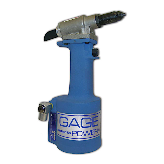
Image may not reflect actual tool
4
REV. 10/14