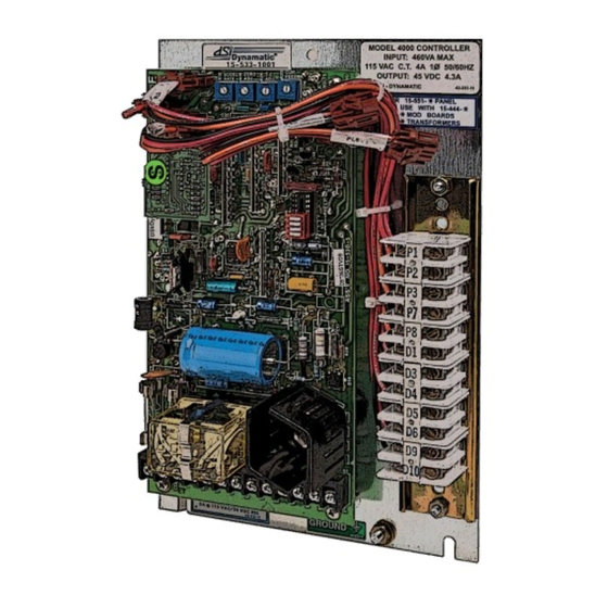
Dynamatic 15-533-1015 Инструктивный лист - Страница 9
Просмотреть онлайн или скачать pdf Инструктивный лист для Контроллер Dynamatic 15-533-1015. Dynamatic 15-533-1015 14 страниц.

d. Check the drive nameplate for motor hp, voltage and current ratings. Set the programming
switches as indicated in Table 1 on the connection diagram for your rated motor current.
4. Place a clamp-on ammeter on one lead of the ac motor
Adjustment Procedure
Caution: To avoid personal injury or damage to the test equipment remove power before connecting or
disconnecting test equipment.
The Model 4000 and 4050 controllers contain an LED status monitor which provides a visual means of
setting the maximum speed and zero adjust. This LED set up along with an alternate method is given
below.
1. Turn ON the power to the drive and start the ac motor
2. Start the controller with the Start pushbutton. Note the location of the Stop pushbutton
3.
Zero Adjust R19 with LED monitor
while monitoring the LED, D22. When controller output is turned on or clutch voltage is turned
ON (or the drive shaft begins to rotate), the LED should start flashing. Now just back off slowly
until the flashing stops.
Zero Adjust R19, Alternate
minimum speed greater than zero, as required by the machine operating requirements.
a. For zero rpm, turn the Zero Adjust potentiometer R19 CW until the output shaft just begins
to turn. Then, back off on the control until the output shaft just stops turning. Stop and start
the controller a few times to be sure the drive shaft does not rotate.
b. For a minimum speed greater than zero, the LED cannot be used. Turn the Zero Adjust
potentiometer CW until the desired speed is attained. For an accurate setting use a
tachometer or stroboscope.
4.
Max Speed/Volts R21-
to a slower speed as required by the machine process. An LED status monitor has been provided
on the main board to allow you to set the maximum speed the tachometer or stroboscope will
give an accurate rpm setting while the use of a voltmeter will give only an approximate speed
setting. This is because the voltmeter is measuring generator voltage instead of actual output
rpm.
Max Speed/Volts R21 with LED monitor
The drive should be loaded for best results. Set the Max Speed/Volts potentiometer R21 at 100%
(Full CW). Caution: drive will go to top speed. The LED should be out when the drive is at top
speed. With the LED out, slowly turn the Max Speed/Volts potentiometer R21 CCW until the LED
lights. This indicates that the speed of the drive is in the regulating range of the controller. The
clutch voltage should drop below 45V. This will be approximately the maximum rated speed of
the drive. The maximum speed point setting will vary with different mechanical units.
9
- Slowly increase the Zero Adjust Potentiometer R19 CW
Method- This adjustment can be set to provide zero rpm or some
This adjustment can be set to limit drive speed to its rated maximum or
Set the Run Speed potentiometer R5 at 100%, (Full CW).
