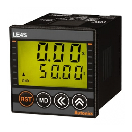
Autonics LE4S Series Инструкция - Страница 12
Просмотреть онлайн или скачать pdf Инструкция для Таймер Autonics LE4S Series. Autonics LE4S Series 18 страниц. Lcd digital timers
Также для Autonics LE4S Series: Руководство (17 страниц), Руководство (6 страниц)

LE4S Output operation mode
Mode
Time chart
[
OND
]
OND
RELAY OUT
UP
DOWN
ON Delay
1. Timing operation starts when START signal is ON at status of power on.
2. Output will be ON when timing operation is progressed up to the setting time. Display value will be
HOLD. (① position)
3. When RESET signal is ON, display value and output will be reset.(② position)
T > Ta
4. If RESET signal is OFF while START signal is ON,"STEP 1"will be restarted.(③ position)
5. When START signal is OFF, display value and output will be reset.(④ position)
[
ONd1
]
ONDⅠ
RELAY OUT
UP
DOWN
ON Delay 1
1. Timing operation starts when START signal is ON at status of power on.
2. Output will be ON when timing operation is progressed up to the setting time. Display value will be
HOLD.(① position)
T > Ta
3. Even though START signal is applied repeatedly, only the initial signal is recognized.(② position)
4. When RESET signal is ON, display value and output will be reset.(③ position)
[
ONd2
]
ONDⅡ
RELAY OUT
UP
DOWN
ON Delay 2
1. Timing operation starts when START signal is ON at status of power on.
(One-shot output)
2. Time limit output will be ON and goes OFF during Tout setting time when timing operation is progressed
up to the setting time. Display value will be HOLD.(① position)
3. When RESET signal is ON, display value and output will be reset.
4. If START signal is applied while time is progressing, Timing operation will be reset and started again. (②
T > Ta
position)
5. Tout setting range: 0.01 sec to 99.99 sec.
[
FLK
]
FK
RELAY OUT
UP
Flicker
DOWN
(Toff operation
precedes)
1. If START signal is ON, output will be repeatedly OFF during Toff setting time and will be OFF during Ton
setting time when power is ON.
2. When RESET signal is ON, display value and output will be reset.
3. If RESET signal is OFF when START signal is ON, "STEP 1" will be restarted.
4. When START signal is OFF, display value and output will be reset.
Ton, Toff > Ta
5. It is able to set each Toff time and Ton time separately. In [
FLk1
[
]
FK. Ⅰ
RELAY OUT
UP
Flicker 1
DOWN
(Ton operation
1. IF START signal is ON, output will be repeatedly ON during Ton setting time and will be OFF during Toff
precedes)
setting time when power is ON.
2. Even though START signal is applied repeatedly, only the initial signal is recognized.(① position)
3. When START signal is ON, display value and output will be reset. If START signal is ON, it will be
Ton, Toff > Ta
restarted.
4. It is able to set each Toff time and Ton time separately. In [
※ Initial status : UP mode-display value is "0", output is "OFF". DOWN mode-display value is "setting time", output is "OFF".
T
POWER
START
RESET
①
Set time
0
Set time
0
T
POWER
START
RESET
①
Set time
0
Set time
0
T
T
POWER
START
RESET
①
Set time
0
Set time
0
Toff
Ton
Toff
Ta
POWER
START
RESET
Toff
Ton
0
Toff
Ton
0
Ton
Toff
Ton
Toff
POWER
START
①
RESET
Toff
Ton
0
Toff
Ton
0
LCD Timer(Touch Type)
T
Ta
T
②
③
T
Ta
T
②
③
Ta
Ta
T
②
Toff
Ta
Toff
Ton
Ta
] mode, timing operation starts with Toff.
Ta
Ton
Toff
Ta
Ton
Ta
] mode, timing operation starts with Ton.
T = Setting time, T > Ta
Operation
④
POWER
START
T
RELAY
OUT
T = set time
POWER
RESET
START
T
RELAY
OUT
T = set time
POWER
START
RELAY
T
OUT
Tout = output time
T = set time
Toff
Ton
POWER
START
Toff Ton Toff Ton
RELAY
OUT
Ton, Toff = set time
Enables to set Ton and
Toff time differently.
Ton
POWER
START
Ton Toff Ton
RELAY
OUT
Ton, Toff = set time
Enables to set Ton and
Toff time differently.
(A)
Photo
electric
sensor
(B)
Fiber
optic
sensor
(C)
Door/Area
sensor
(D)
Proximity
sensor
(E)
Pressure
sensor
(F)
Rotary
encoder
(G)
Connector/
Socket
(H)
Temp.
controller
(I)
SSR/
Power
controller
(J)
Counter
(K)
Timer
(L)
Panel
Tout
meter
(M)
Tacho/
Speed/ Pulse
meter
(N)
Display
unit
(O)
Sensor
controller
(P)
Switching
mode power
supply
(Q)
Stepper
motor&
Driver&Controller
(R)
Graphic/
Logic
panel
(S)
Field
network
device
(T)
Software
(U)
Other
K-31
