Emerson Fisher 249 Руководство по эксплуатации - Страница 5
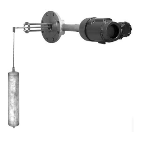
Просмотреть онлайн или скачать pdf Руководство по эксплуатации для Аксессуары Emerson Fisher 249. Emerson Fisher 249 16 страниц. Cageless displacer sensors
Instruction Manual
D200100X012
Process residue buildup on the displacer and stem (key 24) may change displacer weight or displacement. A bent stem
or a dented or corroded displacer can impair performance.
If the displacer rests against the travel stop, appears to be overweight, or causes output drift or other output
inaccuracies, it may have been penetrated by process pressure or liquid. Such a displacer may contain pressure
because it was in a pressurized vessel, may contain process liquid that becomes pressurized due to a change in
temperature, and may contain process liquid that is flammable, hazardous, or corrosive.
WARNING
Sudden release of pressure, contact with hazardous liquid, fire, or explosion, which may result in personal injury or
property damage, can occur if a displacer that is retaining pressure or process liquid is punctured, subjected to heat, or
repaired.
Handle the displacer with care.
Note
On the 249V, 249P, and 249BP with travel stop, the displacer must come out with the sensor head (key 2) or torque tube arm
(key 3) before being completely disconnected from the displacer rod (key 7). If separating the displacer and displacer rod, remove
the cotter spring (key 11).
CAUTION
Be careful not to let the displacer slip and drop into the bottom of the process vessel, as displacer damage could result.
1. Before starting any maintenance procedure, be sure the following safety actions are completed.
D Relieve process pressure in the process vessel where the 249 sensor is installed.
D Drain the process liquid from the process vessel.
D Shut off any electrical or pneumatic input to the controller or transmitter attached to the 249 sensor and vent
any pneumatic supply pressure. Remove the controller or transmitter from the torque tube arm.
D Use caution when loosening flange bolting or pipe plugs.
D Be sure process pressure or liquids have not penetrated the displacer.
2. Support the sensor head (key 2) and the torque tube arm (key 3). Remove the bolting that holds the sensor head to
the process vessel.
CAUTION
When removing a sensor from a process vessel, the displacer may remain attached to the displacer rod and be lifted out
with the sensor head (key 2) when the sensor head is removed. If separating the displacer and displacer rod before
removing the sensor head, remove the cotter spring (key 11). If the displacer comes out with the head or torque tube arm,
be careful not to damage the displacer or bend the stem when setting the head or arm down.
249 Cageless Sensors
July 2015
5