Emerson Fisher 249 Руководство по эксплуатации - Страница 6
Просмотреть онлайн или скачать pdf Руководство по эксплуатации для Аксессуары Emerson Fisher 249. Emerson Fisher 249 16 страниц. Cageless displacer sensors
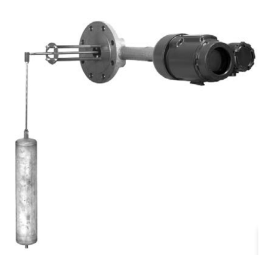
249 Cageless Sensors
July 2015
Be careful not to let the displacer slip and drop into the bottom of the process vessel, as displacer damage could result.
3. Carefully remove the sensor head or torque tube arm.
4. On the 249V, the travel stop plate can be located in one of four positions as shown in figure 3.
For proper operation in the target application, the displacer rod must not touch either plate over the expected
range of process conditions.
D When the displacer is completely submerged in the upper fluid, the net load of weight minus buoyancy must be
low enough to allow the displacer rod to be above the lower plate.
D When the displacer is completely submerged in the lower fluid, the net load of weight minus buoyance must be
high enough to keep the displacer rod from hitting the upper plate.
If necessary, remove the place and choose a position where the rod will not touch the plate.
Figure 3. Fisher 249V Travel Stop Plate Positions
1
HIGH
BJ8646‐A
5. Follow the procedure for replacing the displacer, displacer rod assembly, cotter spring, stem end piece, and
displacer spud as necessary.
Replacing the Displacer, Cotter Spring, Stem End Piece, and Displacer
Spud
The cotter spring (key 11), the ball on the displacer rod/driver assembly (key 7), and the stem end piece or displacer
stem connector (key 23) may be either too worn for a secure connection or so clogged or corroded that the displacer
does not pivot properly. Replace these parts, as necessary.
CAUTION
If the displacer is to be disconnected from the displacer rod before being removed from the process vessel, provide a
suitable means of supporting the displacer to prevent it from dropping into the process vessel and being damaged.
6
2
INTERMEDIATE
Instruction Manual
3
INTERMEDIATE
D200100X012
4
LOW