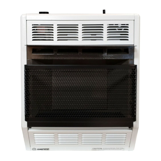
Empire BF-10-1 Инструкции по установке и руководство пользователя - Страница 5
Просмотреть онлайн или скачать pdf Инструкции по установке и руководство пользователя для Нагреватель Empire BF-10-1. Empire BF-10-1 12 страниц.

2. Insert (4) plastic expansion anchors provided into the holes.
3. Tighten (4) #10 x 1" (25mm) screws provided into the plastic
expansion anchors. Do not completely tighten screwheads to
the plastic expansion anchors, leave a 1/8" (3mm) gap between
screwheads and plastic expansion anchors.
4. Mount heater onto the (4) screwheads and complete tightening
the screwheads to the plastic expansion anchors.
Attention! Use the following steps to properly align the upper
louver and the reflector with the heat shield.
a. When replacing upper louver, be sure the bottom lip of upper
louver goes behind the heat shield.
b. When replacing reflector, be sure the top lip of reflector goes in
front of the heat shield.
5. Connect the gas line.
2"
(51)
1 3/32
(28mm)
18 7/8"
(479mm)
2 1/32 (52mm)
4 1/32"
(102mm) MIN
SRS-18* and SRS-30 Floor Stand Installation (Figure 3)
1. Align clearance holes on floor stand with screw holes on bottom of
heater, as shown in Figure 3.
2. Attach floor stand to heater with (4) screws provided with floor
stand.
3. Connect the gas line.
* SRS-18 floor stand can not be used in a bedroom installation.
BF-10 must be wall mounted in a bedroom installation.
Installation on Rugs and Tile
If this appliance is installed directly on carpeting, tile or other combustible
material, other than wood flooring, the appliance shall be installed on a
metal or wood panel extending the full width and depth of the appliance.
R-4973
18"
(457mm)
2"
14"
(51)
(356mm)
22"
(559mm)
2" (51mm)
Figure 2
Figure 3
Attention: Optional SRS-18 and SRS-30 Floor Stand meets re-
quirement.
The base referred to above does not mean the fire-proof base as used on
wood stoves. The protection is for rugs that are extremely thick and light
colored tile.
3 9/16"
(90mm)
1 11/16" (43mm)
TO WALL
Gas Supply (Figure 4)
Check all local codes for requirements, especially for the size and
type of gas supply line required. On Natural gas lines less than 15'
(4.6m) long, use 1/2" (13mm) pipe; on longer runs, use 3/4"
(19mm)iron pipe or equal. On LP gas lines please consult LP gas
supplier.
Installing a New Main Gas Cock
Each appliance should have its own manual gas cock.
A manual main gas cock should be located in the vicinity of the unit.
Where none exists, or where its size or location is not adequate, contact
your local authorized installer for installation or relocation.
Compounds used on threaded joints of gas piping shall be resistant to the
action of liquefied petroleum gases. The gas lines must be checked for
leaks by the installer. This should be done with a soap solution watching
for bubbles on all exposed connections, and if unexposed, a pressure test
should be made.
Never use an exposed flame to check for leaks. Appliance must be
disconnected from piping at inlet of control valve and pipe capped
or plugged for pressure test. Never pressure test with appliance
connected; control valve will sustain damage!
A gas valve and ground joint union should be installed in the gas line
upstream of the gas control to aid in servicing. It is required by the
National Fuel Gas Code that a drip line be installed near the gas inlet.
This should consist of a vertical length of pipe tee connected into the gas
line that is capped on the bottom in which condensation and foreign
particles may collect.
Method of Installing a Tee Fitting Sediment Trap (Figure 5)
The use of the following gas connectors is recommended:
— ANS Z21.24 Appliance Connectors of Corrugated Metal Tubing
and Fittings
— ANS Z21.45 Assembled Flexible Appliance Connectors of Other
Than All-Metal Construction
The above connectors may be used if acceptable by the authority having
jurisdiction.
Figure 4
Figure 5
Page 5
