Empire BF-10-1 Инструкции по установке и руководство пользователя - Страница 6
Просмотреть онлайн или скачать pdf Инструкции по установке и руководство пользователя для Нагреватель Empire BF-10-1. Empire BF-10-1 12 страниц.
Pressure Testing of the Gas Supply System
1. To check the inlet pressure to the gas valve, a 1/8" (3mm) N.P.T.
plugged tapping, accessible for test gauge connection, must be
placed immediately upstream of the gas supply connection to the
appliance.
2. The appliance and its appliance main gas valve must be discon-
nected from the gas supply piping system during any pressure testing
of that system at test pressures in excess of 1/2 psig (3.5 kPa).
3. The appliance must be isolated from the gas supply piping system by
closing its equipment shutoff valve during any pressure testing of the
gas supply piping system at test pressures equal to or less than 1/2
psig (3.5 kPa).
Attention! If one of the above procedures results in pressures in excess
of 1/2 psig (14" w.c.) (3.5 kPa) on the appliance gas valve, it will result
in a hazardous condition.
Checking Manifold Pressure
Natural gas will have a manifold pressure of approximately 3.5"
w.c. (.87kPa) at the pressure regulator outlet with the inlet pressure
to the pressure regulator from a minimum of 5.0" w.c. (1.245kPa) for
the purpose of input adjustment to a maximum of 10.5" w.c.
(2.615kPa). Propane/LP gas will have a manifold pressure approxi-
mately 10.0" w.c. (2.49kPa) at the pressure regulator outlet with the
inlet pressure to the pressure regulator from a minimum of 11.0" w.c.
(2.739kPa) for the purpose of input adjustment to a maximum of
13.0" w.c. (3.237kPa).
A test gage connection is located downstream of the gas appliance
pressure regulator for measuring gas pressure. The connection is a
1/8 inch (3mm) N.P.T. plugged tapping.
High Altitudes
For altitudes/elevations above 2,000 feet (610m), ratings should be
reduced at the rate of 4 percent for each 1,000 (305m) feet above sea
level. Contact the manufacturer or your gas company before chang-
ing spud/orifice size.
Piezo Pilot Ignitor Instructions
Depressing the ignitor button completely causes a spark to occur at the
pilot.
To light the pilot, it is important that the electrode be 1/8" (3mm) from the
pilot. The spark must occur at the point the pilot flame hits the thermo-
couple.
On a new installation with air in the gas line, it is suggested that a match
be used. The match will light the pilot faster than the piezo under this
condition.
Keep appliance area clear and free from combustible materials,
gasoline and other flammable vapors and liquids.
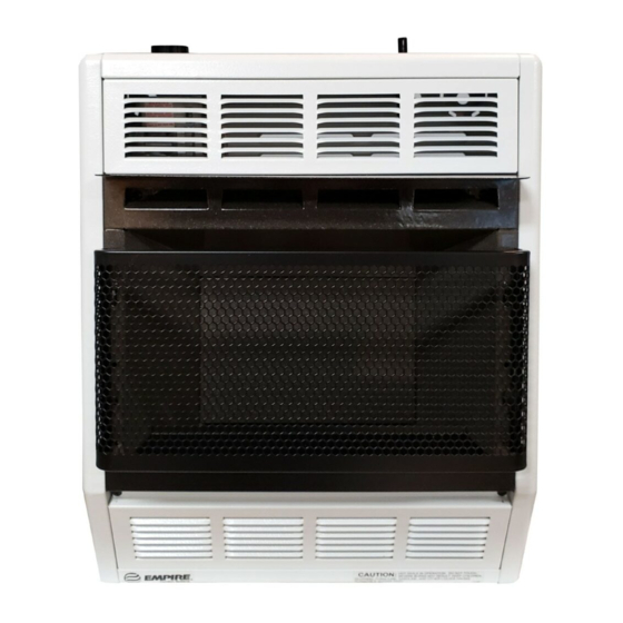
Glass Removal, Cleaning and Glass Replacement
1. Remove chrome grill from reflector.
2. Slide glass upward to remove glass from chrome grill.
3. Clean glass with a non-abrasive household glass cleaner and warm
water. Gas fireplace glass cleaner can also be used.
4. Align glass with rails on chrome grill and slide glass downward into
chrome grill.
5. Attach chrome grill onto reflector.
Warning: Do not operate unvented room heater without
glass/chrome grill attached to reflector.
APPLIANCE MAINTENANCE INFORMATION
FOR QUALIFIED SERVICE PERSON
To Remove Pilot From Main Burner Assembly
1. Turn OFF gas supply to the heater.
2. Turn OFF electrical supply to the heater if optional blower, SRB-
18T or SRB-30T is installed in heater.
3. Remove lower louver from casing assembly (2 screws).
4. Remove reflector from casing assembly (2 screws).
5. Disconnect pilot tubing from pilot (see Figure 8, Page 7). Grasp nut
A with a wrench when removing nut B with a second wrench.
6. Remove pilot from pilot bracket (2 nuts).
7. As parts are being replaced in reverse order, check for gas leaks at
all gas connections before lower louver is replaced onto casing
assembly.
Page 6
To Remove Main Burner Orifice From
Main Burner Assembly
1. Turn off gas supply to the heater.
2. Turn off electrical supply to the heater if optional blower, SRB-18T
or SRB-30T is installed in heater.
3. Remove lower louver from casing assembly (2 screws).
4. Remove reflector from casing assembly (2 screws).
5. Disconnect supply tubing from orifice holder.
6. Remove orifice holder from venturi of main burner assembly.
7. Remove main burner orifice from orifice holder.
8. As parts are being replaced in reverse order, check for gas leaks at
all gas connections before lower louver is replaced onto casing
assembly.
To Remove Gas Valve From Casing Assembly
1. Turn OFF gas supply to the heater.
2. Turn OFF electrical supply to the heater if optional blower, SRB-
18T or SRB-30T is installed in heater.
3. Remove lower louver from casing assembly (2 screws).
4. Remove reflector from casing assembly (2 screws).
5. Remove upper louver from casing assembly (2 screws).
6. If installed, remove optional blower assembly (4 screws).
7. Disconnect inlet supply tubing, outlet supply tubing, pilot supply
tubing and thermocouple lead from gas valve.
8. If heater is attached to wall, disconnect gas supply line from inlet
regulator.
9. Remove heater from wall.
10. Remove gas valve bracket from casing assembly (4 screws to be
removed are located on casing assembly back).
11. Remove hydraulic thermostat bulb from thermostat bulb clip located
at casing assembly bottom.
12. Remove gas valve from gas valve bracket.
13. As parts are being replaced in reverse order, check for gas leaks at
all gas connections before upper louver, reflector and lower louver
are replaced onto casing assembly.
To Remove Main Burner From Casing Assembly
1. Turn OFF gas supply to the heater.
2. Turn OFF electrical supply to the heater if optional blower, SRB-
18T or SRB-30T is installed in heater.
3. Remove lower louver from casing assembly (2 screws).
4. Remove reflector from casing assembly (2 screws).
5. Disconnect supply tubing from orifice holder.
6. Remove main burner assembly from casing assembly (2 screws).
7. Remove air shutter(s) from main burner. BF-10 Natural and LP has
two (2) air shutters, BF-20 LP has one (1) air shutter and BF-30 LP
has one (1) air shutter. Attach air shutter(s) to new main burner
assembly.
8. As parts are being replaced in reverse order, check for gas leaks at
all gas connections before lower louver is replaced onto casing
assembly.
Proper Main Burner Flame (Figure 6)
There will be a short blue inner flame with a much larger, lighter blue,
secondary flame. The burner flame may have a small yellow tip when
hot. Dust in the combustion air will produce an orange or red flame. Do
not mistake the orange or red flame for an improper yellow flame. Clean
main burner by applying compressed air into ports and throat of main
burner.
Figure 6
R-4973