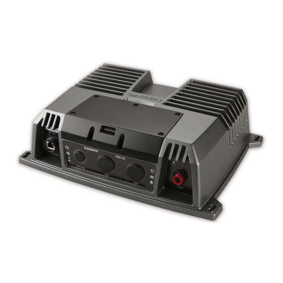
Garmin GSD 26 Руководство по установке - Страница 2
Просмотреть онлайн или скачать pdf Руководство по установке для Морское оборудование Garmin GSD 26. Garmin GSD 26 14 страниц. Professional sonar module
Также для Garmin GSD 26: Руководство по установке (6 страниц), Руководство по установке (6 страниц)

Tools Needed
• Drill
• #8 (5 mm) drill bit for mounting surface
1
• 1
/
in. (32 mm) paddle drill bit or hole saw for mounting surface
4
• #2 Phillips screwdriver
• 3 mm flat screwdriver
• Cable ties (optional)
• Dielectric grease
• Wire cutter
• Wire stripper
19
• 1 in. (24 mm) and
/
32
• Marine sealant (optional)
Mounting the Sounder
Mounting Location Considerations
• The sounder must be mounted in a location where it cannot be submerged.
• The sounder must be mounted in a location with adequate ventilation where it will not be exposed to extreme
temperatures.
• The sounder should be mounted so that the LEDs are visible.
• The sounder should be mounted so that the power and network cables can be easily connected.
• The sounder should be mounted so that the transducer cable can be connected. If required, transducer
extension cables are available through your Garmin dealer.
Mounting the Device
If you are mounting the bracket on fiberglass with screws, it is recommended to use a countersink bit to drill
a clearance counterbore through only the top gel-coat layer. This will help to avoid any cracking in the gel-coat
layer when the screws are tightened.
Stainless-steel screws may bind when screwed into fiberglass and overtightened. Garmin recommends applying
an anti-seize lubricant to the screws before installing them.
Before you mount the device, you must select a mounting location and determine the mounting hardware
needed for the surface.
NOTE: Mounting hardware is included with the device, but it may not be suitable for the mounting surface.
1 Place the device in the mounting location and mark the location of the pilot holes.
2 Drill the appropriate pilot hole for one corner of the device.
3 Loosely fasten the device to the mounting surface with one corner and examine the other three pilot-hole
marks.
4 Mark new pilot-hole locations if necessary, and remove the device from the mounting surface.
5 Drill the appropriate pilot holes for the other three marks.
6 Secure the device to the mounting location.
2
in. (15 mm) wrenches
NOTICE
GSD 26 Installation Instructions
