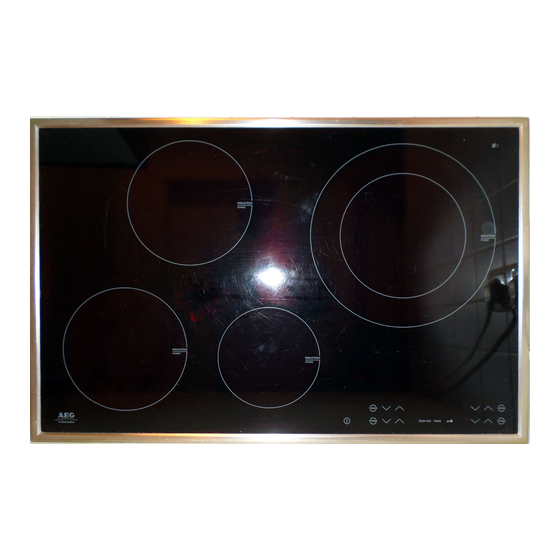
AEG 88101 Руководство по эксплуатации - Страница 4
Просмотреть онлайн или скачать pdf Руководство по эксплуатации для Варочная панель AEG 88101. AEG 88101 22 страницы. Induction hobs

2 Alarm Symptoms
2.1 Appliance not functioning at all, cannot be switched on
References e.g. (1) refer to the illustrations in Chapter 2.8
Alarm Symptom
House fuse triggered
Cooking field cannot
be switched on.
Normally no "pips"
approx. 4 sec. after
mains voltage is
applied
respectively no quick
flashing up of the
display in the cooking
zone with not self-
sufficient cooking
zones or front line
appliances.
Every 5-10 sec "beep"
of touch control
Only Frontline
appliances: cooking
zone can not be
activated. Display fully
on for more than 5 sec.
DGS-TDS
21.04.08
4
Cooking
Possible Alarm
Hob
Cause
Display
None
Incorrect connection at
the power connection
terminal
.
Final induction phase
defect.
None
Electronic system no
longer reacts
No mains voltage or
incorrect connection
(1 phase missing ->no
control voltage; N not
connected to terminal 4
and 5 not connected)
No 5VDC betw. Pin 1 +
3 of the Bus for the
Touch Control
Connector of the cable
to the Touch Control
not inserted.
Display
Fuse strip conductor burnt
out and/or final induction
phase defect
Touch control/display
defect.
None
N not connected to
terminal 4 or 5.
All
Flat band cable
indications
between user interface
ON
and glass (touch
keyboard) not plugged
correctly.
Alarm Remedying
(1) Test the pin assignment and
230VAC between N and the phases on
the supply line.
See chapter 3 Testing Power Component
Disconnect the appliance from the mains
using the house fuse, reactivate after
approx. 10 sec..
(1) Test the pin assignment and
230VAC between 4 N and the 2 phases
on supply line terminals 1 and 2.
Both of the "N"s should be connected to
terminals 4 + 5, if appr. jumper.
(2) Test 1+3 5VDC on the underside of
the cooking field
(corresponds with the external lines of
the bus between filter and Touch
Control), if not applied, replace the
Filterboard.
Caution: this is difficult to test from
underneath using normal test probes!
(3) Test connector at the filter and Touch
Control.
/
Reapply the mains voltage.
See chapter 3 "Check power section'"
If 5VDC exist and power component already
Touch Control, ensure
replaced: replace
that the Touch Control is applied to the
glass
.
(1) Test the pin assignment and
230VAC between 4 N and the 2 phases
on supply line terminals 1 and 2.
Both of the "N"s should be connected to
terminals 4 + 5, if appr. jumper.
Check line for seat and correct position
(contact direction), see capter
"References Frontline"
599 519 523 EN
