Avnet ROHM Semiconductor Руководство пользователя - Страница 4
Просмотреть онлайн или скачать pdf Руководство пользователя для Блок управления Avnet ROHM Semiconductor. Avnet ROHM Semiconductor 8 страниц. Power module

2 Functional Description
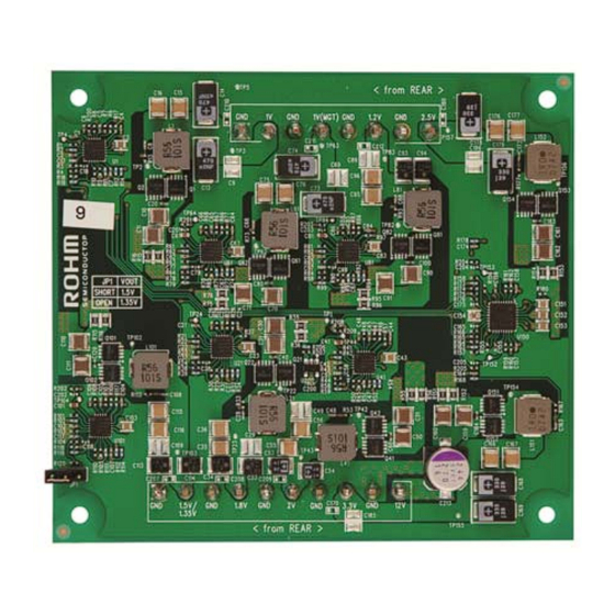
The power module provides 8 sequenced output voltages with controlled rise times from a
12VDC input. The supplies are designed to meet the current and regulation tolerances outlined
in table 1.
2.1 Block Diagram
2.2 Power Module Interfaces
The following tables show the pinouts for J1, J2 and J3. J1 and J2 provide power and ground to
and from the baseboard. J1 (Samtec part # HPM-10-05-T-S) and J2 (Samtec part # HPM-08-
05-T-S) provide power to and from the board. On the baseboard, J1 mates with Samtec part #
HPF-10-01-T-S and J2 mates with Samtec part # HPF-08-01-T-S.
Pin
1
Signal
GND
Pin
Signal
Copyright © 2012 Avnet, Inc. AVNET and the AV logo are registered trademarks of Avnet, Inc. All other brands are property of their respective owners.
Avnet Electronics Marketing
Figure 1 - Block Diagram
2
3
1.5V/1.35V
GND
1
2
3
GND
1V
GND
4
5
6
1.8V
GND
2V
Table 2 - J1 Pinout
4
5
1V(MGT)
GND
Table 3 - J2 Pinout
4 of 8
7
8
9
GND
3.3V
GND
6
7
8
1.2V
GND
2.5V
10
12V
Rev A 1.0
06/05/2013
