Aqua Medic Cubicus CF Qube Руководство по эксплуатации - Страница 6
Просмотреть онлайн или скачать pdf Руководство по эксплуатации для Аквариумы Aqua Medic Cubicus CF Qube. Aqua Medic Cubicus CF Qube 16 страниц.

3.
Overflow system
Fig. 2: Overflow system Cubicus CF Qube
1.
Water inlet to the filter
2.
Nut for
bushing
3.
Slide ring for
bushing
4.
Ball valve
5.
Emergency overflow
6.
Hose connection for re-circulation pump
7.
Slide ring for
bushing
8.
Nut for
bushing
9.
Ventilation angle
10.
Adjustable joint for return line
Available spare parts: Please refer to www.aqua-medic.de.
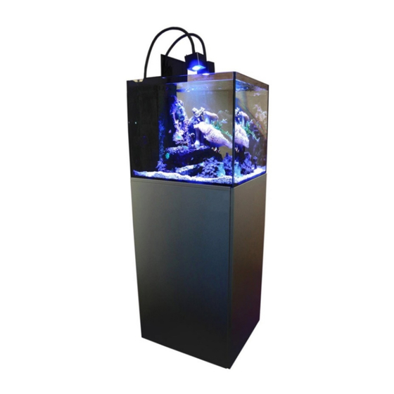
In the Cubicus CF Qube, there is an overflow system behind the black panel to which the light is mounted. The
system consists of an overflow shaft with combs, a slotted pipe through which the water enters the filter, an
emergency overflow and a return line placed next to the overflow shaft. In the cabinet, there is a ball valve that
has to be slightly closed to control the water in the overflow box. If the valve is closed to heavily or the return
flow is blocked for some reason, the water rises in the aquarium and flows to the filter tank through the emergency
overflow. In such a case, the ball valve has to be opened a bit further and all blockages have to be eliminated. If
the overflow makes loud noises, the ball valve has to be closed a bit more so the water is bottled up stronger so
that no air is dragged along. At least in the initial phase this has to be controlled regularly and, if necessary, to
be adjusted.
With the supplied PVC tubes with moulded keys on one side for holding the nuts of the bushings (tank fittings),
these nuts can be tightened or released in the overflow box or aquarium. The bushings have to be installed
according to Fig. 2. Always re-tighten before use. The nut of the emergency overflow has to be screwed from the
bottom. The PVC tube key can be pushed out of the chamber of the filter tank from underneath over the tube of
the emergency overflow. The slide ring and nut have to be mounted manually beforehand and tightened as much
as possible. The rubber slide ring must always be attached to the side of the rotable nut, the rubber gasket on
the opposite side of the panel.
Fig. 3: Bushing or tank fitting (the glass pane is placed between slide ring 3 and rubber ring 2)
6
