Dell PowerVault MD3060e Series Руководство пользователя - Страница 13

Просмотреть онлайн или скачать pdf Руководство пользователя для Хранение Dell PowerVault MD3060e Series. Dell PowerVault MD3060e Series 40 страниц. Storage enclosure
Также для Dell PowerVault MD3060e Series: Руководство по аппаратному и программному обеспечению (25 страниц), Руководство по установке (11 страниц), Руководство по началу работы (10 страниц), Обновление информации (8 страниц), Инструкции по установке стоек (2 страниц), Настройка (2 страниц), Руководство по развертыванию (24 страниц), Руководство администратора (35 страниц), Руководство по началу работы (10 страниц), Руководство по развертыванию (24 страниц), Руководство администратора (48 страниц), Настройка (2 страниц)
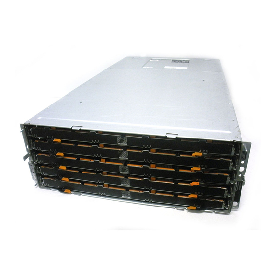
Dell PowerVault MD3060e Series Руководство пользователя
Item
Indicator, Button, or
Connector
1
SAS IN port 0
2
SAS IN port 1
3
Serial debug port
4
Telnet port
5
SAS OUT port
6
Diagnostic LED
7
Module power indicator
8
Service action required
indicator (system)
9
Service action allowed
indicator

Storage Enclosure Thermal Shutdown

The system automatically shuts down when system temperature exceeds the safe threshold.
Temperature threshold values determine the temperature at which shutdown occurs. These thresholds
cannot be changed. The system will attempt to auto-restart after returning to normal temperatures.

Related Documentation

WARNING: See the safety and regulatory information that shipped with your system. Warranty
information may be included within this document or as a separate document.
Icon
Description
For SAS connection of the storage enclosure to a server,
RAID controller, or another storage enclosure.
For SAS connection of the storage enclosure to a server,
RAID controller, or another storage enclosure.
Dell support only.
Dell support only.
For connection to additional storage enclosures.
The numeric display consists of two seven-segment LEDs
that provide information about enclosure identification
and diagnostics.
The module power indicator lights green when module
power is on.
The Service action required indicator lights amber when
there is a fault in one of the components in the system.
CAUTION: Remove the expansion module from the
system only if the Service action allowed indicator
lights blue. Removing the expansion module from
the system when the Service action allowed
indicator is off may damage the system.
NOTE: The Service action allowed indicator LED is
not used in server attached configurations.
Blue
Off
Indicates that you can safely
remove the expansion module
from the system.
Indicates that you cannot remove
the expansion module from the
system.
13