HP ProCurve 1600M Руководство рецензента - Страница 10

Просмотреть онлайн или скачать pdf Руководство рецензента для Переключатель HP ProCurve 1600M. HP ProCurve 1600M 27 страниц. Redundant power supply
Также для HP ProCurve 1600M: Технический паспорт (12 страниц), Прочитай меня сначала (8 страниц), Дополнительное руководство (2 страниц), Дополнительное руководство (2 страниц), Руководство по установке (28 страниц), Руководство по установке (36 страниц), Руководство по установке (28 страниц), Руководство по быстрой настройке (2 страниц), Руководство по быстрой настройке (4 страниц), Руководство пользователя (8 страниц), Дополнение к руководству (28 страниц), Прочитай меня сначала (16 страниц), Установка и удаление (2 страниц), Руководство по установке (12 страниц), Руководство по планированию и реализации (40 страниц), Инструкции по разборке изделия в конце срока службы (2 страниц), Руководство по установке (46 страниц), Руководство по диагностике (2 страниц), Инструкции по разборке (2 страниц)
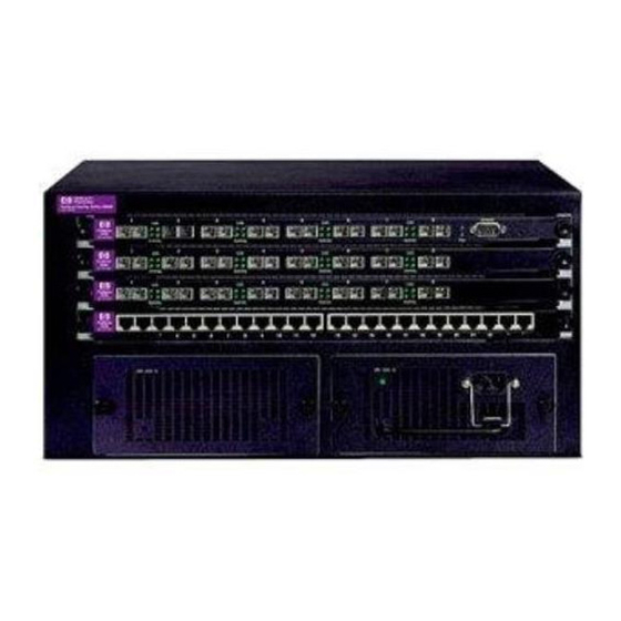
HP ProCurve 1600M Руководство рецензента
HP ProCurve Routing Switch 9308M / 9304M Reviewer's Guide

2.2.4 Forwarding Engine

The forwarding engine, a custom ASIC present on each module, uses the information in the FID to
actually move the packets to and from either external ports or the backplane switch fabric via the
shared memory. The forwarding engine also determines the priority queue (described in the next
section) designation for outbound packets. The forwarding engine has its own separate data path to
the packet processors to make packet processing time as short as possible.

2.2.5 Priority Queues

Priority queues form part of the QoS implementation in the routing switch. Each external port on a
module has 4 priority queues that define the order outbound packets will be sent to that port. There are
also 4 priority queues on the module for each of the other modules installed in the chassis. These are
used for packets destined to travel the backplane to another module. The priority queues themselves
only contain the SMIDs as pointers to the actual packets in shared memory.
These priority queues map into the priority designation of 802.1p. Since 802.1p has 8 levels of priority
possible, 802.1p priority levels 0 and 1 map to the module priority of 0 (lowest), 802.1p levels 2 and 3 to
module priority 1, and so on. Packets without any 802.1p tagging are normally assigned module
priority 0, unless the port priority factors have been modified through user configuration. The priority
queues are managed through a fair-weighted queuing algorithm that prevents any priority queue from
getting starved due to high traffic levels in other queues.
Through user configuration, priority of packets can be changed based on the packet's MAC address,
VLAN affiliation, port the packet came in on, IP address, or IP port number.

2.2.6 System Management Interface

The System Management Interface, present on the management card, stores and maintains the port and
system-level master configuration tables, routing tables, Layer 2, Layer 3, and Layer 4 address tables,
and all FID registers. Packet functions requiring processor attention, such as AppleTalk routing or
broadcast packet handling are also handled through this interface.
Communication from the individual module packet processors to the System Management Interface is
done through the management bus, a control path distinct from the packet data path. Any modification
of the FID for those packets requiring additional central processor attention are also handled through
the management bus. The central processor runs at 240 MHz.
The System Management Interface has 32 MB of DRAM memory available. This memory is used for
switch tables, such as routing tables, ARP cache and MIB tables. At factory default, many of the table
sizes are less than their maximum in order to conserve memory. Tables can be resized through user
configuration, if necessary. Default and maximum values are given in this guide for some tables.

2.2.7 Backplane Design

The modules are interconnected through a backplane crosspoint
Slot 1
switch matrix, allowing packets a direct path to their destination
8 Gbps fdx
module. Each module in the chassis has an 8 Gbps path in both
directions to this matrix.
Slot 2
Slot 3
The advantage of a crosspoint matrix is that all modules can send
packets to every other module simultaneously. The crosspoint
matrix can handle about 22 Mpps in the 9304M and 44 Mpps in the
9308M.
Slot 4
©1999 Hewlett-Packard Company
Revision 4.0 – 4/1/1999
27
Page: 10 of