ABB ACS550 Series Дополнительное руководство по установке - Страница 6
Просмотреть онлайн или скачать pdf Дополнительное руководство по установке для Контроллер ABB ACS550 Series. ABB ACS550 Series 16 страниц. Drive it low voltage ac drives 150...550 hp
Также для ABB ACS550 Series: Краткое руководство по эксплуатации (2 страниц), Краткое руководство по эксплуатации (2 страниц), Руководство пользователя (14 страниц)
6
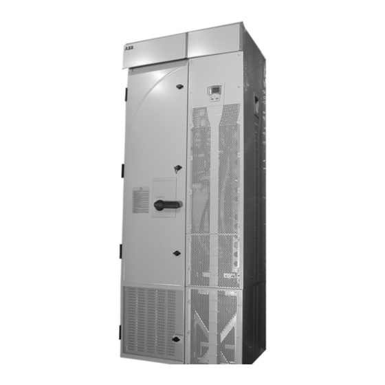
Mounting
Fastening the Unit
See the "Dimensional Drawings" in the "Technical Data" section of this document for
the exact locations of the mounting points.
1. Use at least four screws – two at the front, two at the back – to attach the unit base
plate to the floor.
2. Use at least two screws to attach the back of the enclosure to a wall.
There are two holes available at the top of each: the extension module and the drive
module.
Connecting Power and Control Cables
Additional considerations that apply with the enclosure extension:
• The power cable connection diagram that applies for the ACS550-U2 is:
• Temporarily remove the upper high voltage shield (clear plastic) to gain access to
the power connections in the extension module.
• To avoid metal shavings inside the cabinet, temporarily remove the gland/conduit
plate at the top of the extension module. Then drill holes and mount conduit or
cable fittings as needed.
Installation
Extension Module
OMIO
3
Switch-fuse
Disconnect
3
U1
V1
W1
Control
Wiring
L1 L2
L3 PE
Supply
Installation Supplement for ACS550-U2 Drives
ACS550-02
Drive Module
3
U2
V2
W2
PE
V1
W1
U1
PE
3 ~
Motor
Control
Panel