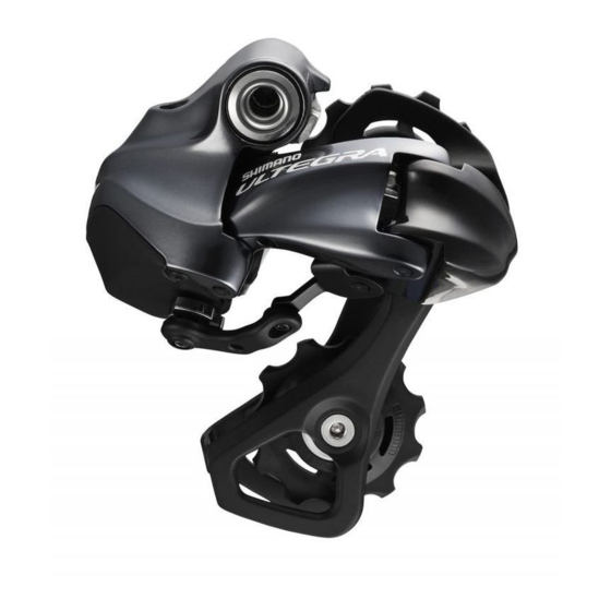
Shimano Ultegra 6770 Series Руководства - Страница 20
Просмотреть онлайн или скачать pdf Руководства для Велосипед Shimano Ultegra 6770 Series. Shimano Ultegra 6770 Series 24 страницы.

OTHER FUNCTIONS
$ Battery charge display function
Press and hold either shifting switch for 0.5 seconds or more. You can check the amount of battery charge remaining using the
battery indicator on junction (A).
Battery indicator
100 %
50 %
25 %
0 %
* When the battery charge is low, first the front derailleur will stop operating, and then the rear derailleur will stop operating.
When the battery charge has been fully spent, the derailleurs will be fixed at the last gear shifting position. If the battery
indicator is illuminated red, it is recommended that you recharge the battery as soon as possible.
$ Protection function
* Rotate the front chainwheel while restoring operation after the protection function has been activated.
If the bicycle receives a strong impact, the protection function operates and the connection between the motor and the link is
momentarily severed so that the rear derailleur will no longer operate. This is done in order to protect the system at times such as if
the bicycle falls over. If this happens, press the rear derailleur adjustment button on junction (A) of the SM-EW67-A-E for 5 seconds
or more. This will restore the connection between the motor and the link and clear the protection function for the rear derailleur.
If the connection is not restored, push/pull the cage sideways or move it forward and backward by hand. Operate the shifting
switches to check that the connection has been restored.
Junction (A)
Rear derailleur adjustment
button
Button hold down
Illuminates (red)
Approx. 5 seconds in total
When the red LED on junction (A) is illuminated, the rear derailleur cannot shift gears. Keep pressing the rear derailleur adjustment
button until the red LED turns off.
38
Illuminates green (for 2 seconds)
Flashes green (5 times)
Illuminates red (for 2 seconds)
Flashes red (5 times)
Illuminates (red)
Flashes (red)
Protection clear operation
Protection cleared
MAINTENANCE
$ Disassembly of the bracket unit and lever unit
1.
Use the special tool which is sold separately to remove the E-ring.
Align part B of the special tool with the removal direction of the E-ring. Next, set part A onto the E-ring and remove the E-ring.
Note:
* The E-ring may fly off suddenly during removal, so check that there are no people or objects nearby while
removing the E-ring.
2.
Insert an Allen key or a similar tool into the hole in the lever stud, and then
tap it with a plastic mallet to push out the lever stud.
3.
Remove the return spring.
* The illustrations show the right-side lever.
(A)
Special E-ring
removal tool
Y6RT68000
(B)
Lever stud
Return spring
39
