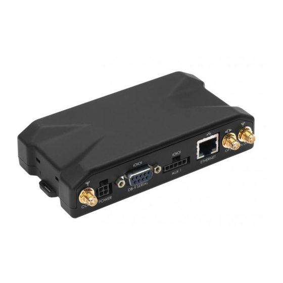
Actsoft LMU-5000 Руководство по установке оборудования - Страница 6
Просмотреть онлайн или скачать pdf Руководство по установке оборудования для GPS Actsoft LMU-5000. Actsoft LMU-5000 8 страниц.

I/O Descriptions
The LMU-5000™ provides the following inputs and outputs (I/O):
Digital Inputs
Input 0: Ignition Sense (Always biased low)
Input 1: Generic Digital Input (Biased high or low/ S-158 Bit 1)
Input 2: Generic Digital Input (Biased high or low/ S-158 Bit 2)
Input 3: Generic Digital Input (Biased high or low/ S-158 Bit 3)
Input 4: Generic Digital Input (Biased high or low/ S-158 Bit 4)
Input 5: Generic Digital Input (Biased high or low/ S-158 Bit 5)
Input 6: Generic Digital Input (Biased high or low/ S-158 Bit 6)
Input 7: Generic Digital Input (Biased high or low/ S-158 Bit 7)
Analog to Digital Inputs
A/D 0: External Power Supply Monitor
A/D 1: External A/D Input (From Power Connector)
A/D 2: External A/D Input (From 22 Pin I/O Conenctor)
A/D 3: External A/D Input (From 22 Pin I/O Conenctor)
A/D 4: External A/D Input (From 22 Pin I/O Conenctor)
A/D 5: External A/D Input (From 22 Pin I/O Conenctor)
A/D 6: GPS Antenna Sense
A/D 7: LMU-5000, Internal Temp Monitor
Outputs:
Output 0: Standard Open Collector Relay Output
Output 1: Standard Open Collector Relay Output
Output 2: Standard Open Collector Relay Output
Output 3: Standard Open Collector Relay Output
Output 4: Standard Open Collector Relay Output
Output 5: LED Driver Output 1
Output 6: LED Driver Output 2
iButton / 1 Bit Bus
iButton ID Support
1Wire bus with current boost for temperature sensors
