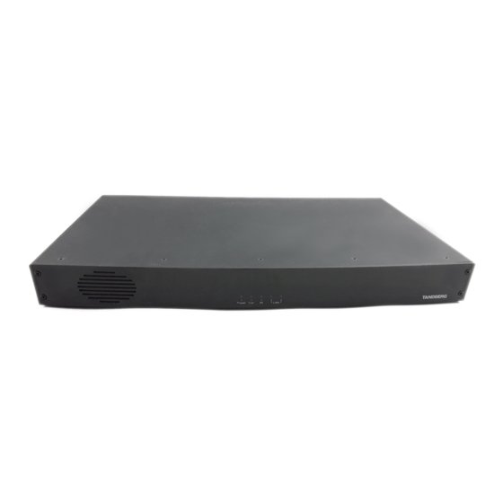
Cisco MXP Series Руководство по физическому интерфейсу - Страница 24
Просмотреть онлайн или скачать pdf Руководство по физическому интерфейсу для Конференц-система Cisco MXP Series. Cisco MXP Series 28 страниц.

MXP Series Codecs
Contents
Net socket (applies to 3000 MXP Net only)
V35 DTE to DCE
Pin
Signal name
Direction
Description
↔
1
FGND
Frame GND on equipment
→
11
SD(A)
Send Data / Transmit
→
12
SD(B)
Send Data / Transmit
←
13
RD(A)
Receive Data
←
14
RD(B)
Receive Data
←
15
SCR(A)
Signal Clock Receive
←
16
SCR(B)
Signal Clock Receive
←
17
SCT(A)
Signal Clock Transmit
←
18
SCT(B)
Signal Clock Transmit
↔
19
GND
Signal GND
1
←
22
RLSD(CD)
Received Line Signal Detector / Carrier Detect
23
RLSD(GND)
1
Signal GND - This pin is connected to ground
←
for correct operations
←
24
RI
Ring Indicator
→
25
LOS
Loss of Signal (KG194)
→
26
DTR
Data Terminal Ready
RS449 DTE to DCE
Pin
Signal name
Direction
↔
1
FGND
Frame GND - Frame GND is connected to pin
1 on DTE
→
11
SD(A)
Send Data
→
12
SD(B)
Send Data
←
13
RD(A)
Receive Data
←
14
RD(B)
Receive Data
←
15
RT(A)
Receive Timing
←
16
RT(B)
Send Timing
←
17
ST(A)
Send Timing
←
18
ST(B)
Send Timing
↔
19
GND
GND - 1) This pin is connected to ground for
1
correct operations
→
20
TR(A)
Terminal Ready
→
21
TR(B)
Terminal Ready
←
22
RR(A)
Carrier Detect / Receiver Ready
←
23
RR(B)
Carrier Detect / Receiver Ready
←
24
IC
Incoming Call
→
25
LOS
Loss of Signal (KG194)
D14790.01 MXP Series Codec Physical Interface Guide, May 2011.
© 2011 Cisco Systems, Inc. All rights reserved.
Introduction
Description
Codec 6000 MXP
Note the following:
V.10 (RS423): For balanced signals a 0 = low
voltage, is defined as terminal A positive with
respect to terminal B. For unbalanced signals a
0 = low voltage, is defined as terminal positive
with respect to GND. Cable length for Leased
Line Control should not exceed 20 m.
RS 366: All balanced inputs and outputs (A
and B) use balanced line signals according to
V.11 (RS 422), while single ended signals are
in accordance with V.10 (RS423). The 0 = low
voltage definitions are the same as for V.10
above. Max cable length, as for V.10 above.
X.21: Signals are as for RS 366 above. Cable
length should not exceed 50 m.
HD D-SUB 26 pin-out
External view of socket
1
9
10
18
19
26
X.21 DTE to DCE
Pin
Signal
Direction
Description
name
↔
1
FGND
Frame GND
→
11
T(A)
Send Data / Transmit
→
12
T(B)
Send Data / Transmit
←
13
R(A)
Received Data / Receive
←
14
R(B)
Received Data / Receive
←
15
S(A)
Signal Element Timing
←
16
S(B)
Signal Element Timing
→
20
C(A)
Terminal Ready / Control
→
21
C(B)
Terminal Ready / Control
←
22
I(A)
Carrier Detect
←
23
I(B)
Carrier Detect
24
Physical interface guide
Codec 3000 MXP
Codec 3000 MXP
Net interface socket. 1 × X.21
/ V.35 / RS449 with 1 × RS366
Call Control up to 2 Mbps
RS366 DTE to DCE
Pin
Signal
Direction
name
↔
1
FGND
→
2
DPR
←
3
ACR
→
4
CRQ
←
5
PND
←
6
DLO
→
7
NB1
→
8
NB2
→
9
NB4
→
10
NB8
Contact us
Description
Frame GND
Digit Present
Abandon Call & Retry
Call Request
Present Next Digit
Data Line Occupied
Digit Bit 1
Digit Bit 2
Digit Bit 4
Digit Bit 8
www.cisco.com
