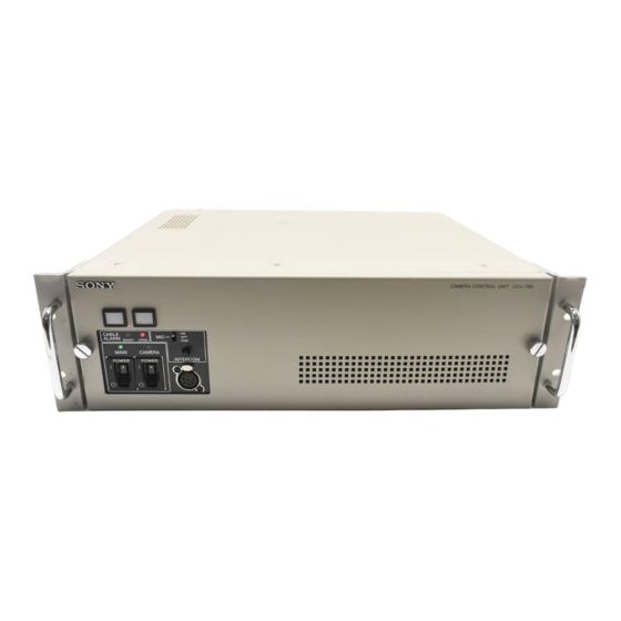
Sony CCU-790P Руководство по эксплуатации - Страница 7
Просмотреть онлайн или скачать pdf Руководство по эксплуатации для Видеокамера Sony CCU-790P. Sony CCU-790P 18 страниц. Camera control unit
Также для Sony CCU-790P: Брошюра и технические характеристики (14 страниц)

B RET-1 (return video signal 1) connectors (BNC
type)
The upper connector accepts return video signal. The input
signal is output from the lower connector.
For details on the selection of RET-1, refer to Operation
Manual that came with the camera or camera adaptor.
C RET-2 (return video signal 2)/PROMPTER
connectors (BNC type)
The upper connector accepts return video signal or
teleprompter signal. The input signal is output from the
lower connector. The signal is split and output to the RET-
2 and PROMPTER signal lines.
For details on the selection of RET-2, refer to Operation
Manual that came with the camera or camera adaptor.
Use the switch on the internal board to output the prompter
signal.
For details on the internal boards, consult your Sony
service personnel.
D SDI (serial digital interface) RET-3/4 (return video
signal 3/4) connectors (BNC type)
Accept SDI return video signal. (These connectors are not
loop-through connectors.)
For details on the selection of RET-3 or RET-4, refer to
Operation Manual that came with the camera or camera
adaptor.
E COAX (coaxial) connector (BNC type)
Accepts and supplies signal from/to the video camera
using a coaxial cable. Power is not supplied to the camera
or a camera adaptor through this connector.
To use this connector, it is required to change the setting of
the internal board. For details, consult your Sony service
personnel.
F SPARE connector (BNC type)
Not used.
d OUTPUT connectors
A VBS/SDI-1, VBS/SDI-2, VBS/SDI-3
connectors
B Y/G, R-Y/R, B-Y/B connectors
C PIX connector
D SYNC connector
E WF connector
A VBS (composite video signal)/SDI (serial digital
interface)-1, VBS/SDI-2, VBS/SDI-3 connectors
(BNC type)
Supply the signal from the video camera in composite or
SDI format.
Use the switch on the internal board to select the composite
video signal or SDI signal.
For details on the internal boards, consult your Sony
service personnel.
B Y/G, R-Y/R, B-Y/B (component video signal/RGB
output) connectors (BNC type)
Supply the component signals or the R, G, and B signals
for the chroma keyer from each connector.
Use the switch on the internal board to select the signals to
be output.
For details on the internal boards, consult your Sony
service personnel.
C PIX (picture monitor output) connector (BNC type)
Supplies a video signal or video and character signals
together to a picture monitor.
Use the WF/PIX Select menu (in MSU-950, RCP-750/
751, or RM-B750) or the PICTURE MONITOR button (on
MSU-900) to select the signal output from the PIX
connector. When the output signal is changed on the RCP-
750/751 or the RM-B750, the waveform output on the
waveform monitor also changes.
D SYNC connector
Connect to the synchronous signal input connector on a
waveform monitor or picture monitor.
E WF (waveform monitor output) connector (BNC
type)
Supplies a video signal to a waveform monitor.
Use the WF/PIX Select menu (in MSU-950, RCP-750/
751, or RM-B750) or the WAVEFORM MONITOR button
Function and Location of Parts and Controls
7
