Cisco 7606 Руководство пользователя - Страница 7
Просмотреть онлайн или скачать pdf Руководство пользователя для Сетевое оборудование Cisco 7606. Cisco 7606 28 страниц. User guide
Также для Cisco 7606: Брошюра (8 страниц)

The cryptographic boundary does not include the network module or service module itself unless it
performs approved cryptographic functions. In other words, the cryptographic boundary encompasses
all hardware components within the chassis except any installed nonapproved cryptographic network
modules or service modules and the power supply submodules. Service modules that are currently
available include the Network Access Module (NAM), a Firewall Services Module, and a VPN Services
Module. All of the functionality described in this publication is provided by components within this
cryptographic boundary.
The service modules require that a special opacity shield be installed over the intake-side air vents in
order to operate in FIPS-approved mode. The shield decreases the surface area of the vent holes,
reducing visibility within the cryptographic boundary to FIPS-approved specifications. Detailed
installation instructions for the shield are provided in this publication.
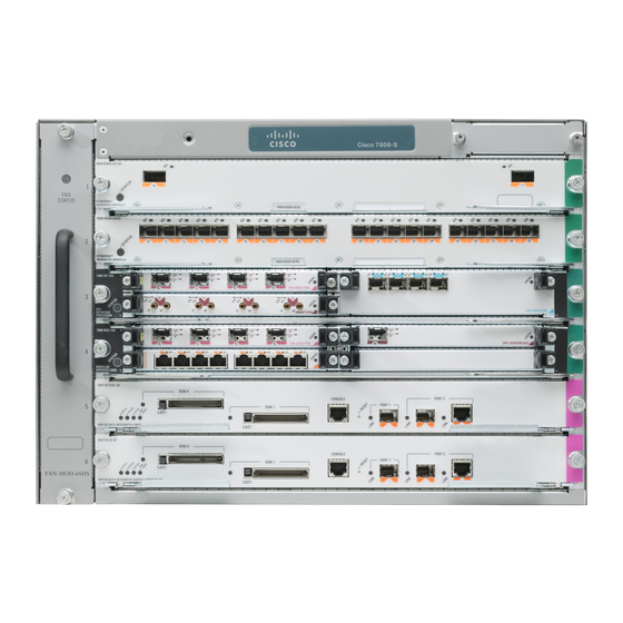
The Catalyst 6509 switch and the Cisco 7606 and Cisco 7609 routers incorporate a single VPN Services
Module cryptographic accelerator card. The VPN Services Module is installed in a chassis module slot.
Cisco IOS features such as tunneling, data encryption, and termination of remote access WANs using
IPsec, Layer 2 forwarding and Layer 2 tunneling protocols make the Catalyst 6509 switch and the
Cisco 7606 and Cisco 7609 routers with VPN Services Module an ideal platform for building virtual
private networks or outsourced dial solutions. The RISC-based processor provides the power needed for
the dynamic requirements of the remote branch office.
Module Interfaces
The switch and router chassis physical interfaces are located on the supervisor engine front panel. (See
Figure
Figure 4
CONSOLE port
WS-X6K-SUP2-2GE
SUPERVISOR2
Status
LEDs
The Catalyst 6509 switch and the Cisco 7606 and Cisco 7609 routers provide console ports, fixed
Ethernet interfaces, nine network and service module slots on the Catalyst 6509 switch and Cisco 7609
router chassis, and six network and service module slots on the Cisco 7606 router chassis. Network
modules support a variety of LAN and WAN connectivity interfaces, such as the following: Ethernet,
ATM, serial, ISDN BRI, and integrated CSU/DSU options for primary and backup WAN connectivity.
An network module or a service module is installed in one of the chassis slots, which are located on the
front panel of the chassis. The modules interface directly with the supervisor engine, and cannot perform
cryptographic functions; they only serve as a data input and data output physical interface.
The supervisor engine has two Ethernet uplink ports. The supervisor engine also has an RJ-45 connector
for a console terminal for local system access. The Ethernet ports have LINK LEDs. Power is supplied
to the module from the power supply through the backplane.
Catalyst 6509 switch and the Cisco 7606 and Cisco 7609 routers.
OL-6334-01
4.)
Supervisor Engine Physical Interfaces
PCMCIA LED
CONSOLE
PORT
MODE
CONSOLE
CONSOLE PORT
PCMCIA slot
MODE switch
RESET button
Catalyst 6509 Switch, Cisco 7606 Router, and Cisco 7609 Router with VPN Services Module Certification Note
Catalyst 6509/Cisco 7606/Cisco 7609 Cryptographic Module
Switch load
display
Switch
Load
100%
PCMCIA
EJECT
1%
1000BASE-X GBIC
Uplink Ports
PORT 1
PORT 2
LINK LEDs
Figure 4
shows the LEDs located on the
Table 1
describes the LEDs.
7
