Cisco ASA 5506-X Руководство по установке оборудования - Страница 22

Просмотреть онлайн или скачать pdf Руководство по установке оборудования для Сетевое оборудование Cisco ASA 5506-X. Cisco ASA 5506-X 26 страниц. Threat defense reimage guide
Также для Cisco ASA 5506-X: Краткое руководство по эксплуатации (10 страниц), Краткое руководство по эксплуатации (14 страниц), Руководство по простой настройке (11 страниц), Руководство по программному обеспечению (37 страниц), Монтаж и подключение (12 страниц), Руководство по установке (46 страниц), Установите шасси (10 страниц)
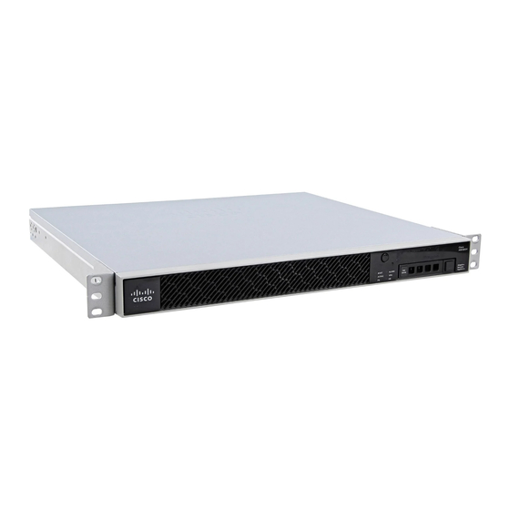
Cisco ASA 5506-X Руководство по установке оборудования

Connect Cables, Turn on Power, and Verify Connectivity

Connect Cables, Turn on Power, and Verify Connectivity
After positioning or mounting the ASA, follow these steps to connect cables, turn on power, and verify
connectivity:
Step 1
Connect the network cables:
a) Management interface – Using this Management 1/1 Gigabit Ethernet port, you can connect a management computer
directly with an Ethernet cable, or you can connect the computer and the ASA to the same management network. Be
sure the PC is configured to obtain an IP address using DHCP.
You can configure any of the Gigabit Ethernet interfaces to be a management-only interface using the
management-only command. However, you cannot disable management-only mode on the Management 1/1 interface.
The following figure shows how to connect the network cables.
1
3
b) (Optional) Console port – For use with the CLI. Connect a computer or terminal server using a serial console cable
to either the RJ-45 or Mini USB Type B port.
Only one console port can be active at a time. When a cable is plugged into the USB console port, the RJ-45 port
becomes inactive. Conversely, when the USB cable is removed from the Mini USB Type B port, the RJ-45 port
Cisco ASA 5506-X Hardware Installation Guide
18
Gigabit Ethernet data interface (RJ-45)
Management 1/1 interface (RJ-45)
2
Console port (RJ-45 or Mini USB Type B)
Mount and Connect the ASA
Online Only