Cisco ATA 191 Руководство пользователя - Страница 7

Просмотреть онлайн или скачать pdf Руководство пользователя для Сетевое оборудование Cisco ATA 191. Cisco ATA 191 30 страниц. Analog telephone adapter
Также для Cisco ATA 191: Руководство пользователя (30 страниц), Руководство по администрированию (4 страниц), Руководство пользователя (10 страниц), Начать (8 страниц), Руководство (10 страниц), Краткое руководство по эксплуатации (13 страниц), Руководство по настройке (6 страниц), Руководство пользователя (40 страниц)
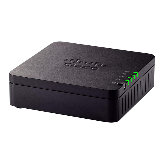
Cisco ATA 191 Руководство пользователя
Get Started with Your New ATA
Item
Phone 1 LED
Phone 2 LED
Problem Report Tool (PRT) Button
Problem Report Tool (PRT) LED

ATA 191 Back Panel

The back panel of your ATA has several ports used to connect your device and to power it. The back panel
also has the reset button for resetting the device to the factory settings.
Figure 2: ATA 191 Back Panel
The following table describes the ports that are located on the back panel of your ATA.
Description
Steady green: On hook.
Slow flashing green: Off hook.
Fast flashing green three times, then repeats: The analog device failed
to register.
Fast flashing green: A factory reset is performed successfully.
Off: The port is not configured.
Press this button to create a problem report using the Problem Report
Tool.
Note
Flashing amber: The PRT is preparing the data for the problem report.
Fast Flashing amber: The PRT is sending the problem report log to
the PRT server.
Solid green for five seconds, then off: The PRT report was sent
successfully.
Fast flashing green: A factory reset is performed successfully.
Flashing red: The PRT report failed. Press the PRT button to turn the
LED off. Once it is off, another press triggers a new PRT report.
Cisco ATA 191 Analog Telephone Adapter User Guide for Cisco Unified Communications Manager
This is not a power button. When you press this button, a
problem report is generated and uploaded to a server for
the system administrator.
ATA 191 Back Panel
3